Toyota Corolla Cross: Replacement
REPLACEMENT
CAUTION / NOTICE / HINT
The necessary procedures (adjustment, calibration, initialization, or registration) that must be performed after parts are removed and installed, or replaced during the front drive shaft oil seal LH and front drive shaft oil seal RH removal/installation are shown below.
Necessary Procedures After Parts Removed/Installed/Replaced|
Replacement Part or Procedure |
Necessary Procedures |
Effect/Inoperative Function When Necessary Procedures are not Performed |
Link |
|---|---|---|---|
|
CVT fluid |
ATF thermal degradation estimate reset |
The value of the Data List item "ATF Thermal Degradation Estimate" is not estimated correctly |
|
|
Bleed air from oil pump (continuously variable transaxle assembly) |
Stop and start system |
|
|
|
Front wheel alignment adjustment |
|
|
|
|
Suspension, tires, etc. |
Rear television camera assembly optical axis (Back camera position setting) |
Parking assist monitor system |
|
|
Initialize headlight ECU sub-assembly LH |
Automatic headlight beam level control system |
|
PROCEDURE
1. REMOVE FRONT DRIVE SHAFT ASSEMBLY
Click here .gif)
2. REMOVE FRONT DRIVE SHAFT OIL SEAL LH
|
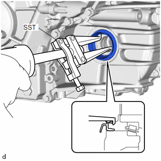
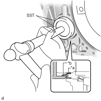
(a) Using SST, remove the front drive shaft oil seal LH from the continuously variable transaxle assembly. SST: 09308-00010 NOTICE: Do not damage the continuously variable transaxle assembly. |
|
3. REMOVE FRONT DRIVE SHAFT OIL SEAL RH
|
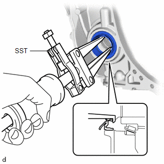
(a) Using SST, remove the front drive shaft oil seal RH from the continuously variable transaxle assembly. SST: 09308-00010 NOTICE: Do not damage the continuously variable transaxle assembly. |
|
4. INSTALL FRONT DRIVE SHAFT OIL SEAL LH
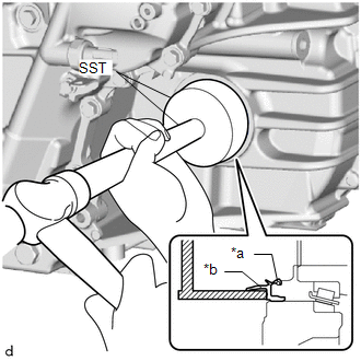
(a) Using SST and a hammer, install a new front drive shaft oil seal LH to the continuously variable transaxle assembly.
|
*a |
Inner Lip |
|
*b |
Outer Lip |
SST: 09950-70010
09951-07150
SST: 09649-17010
Standard Depth:
-0.5 to 0.5 mm (-0.0197 to 0.0197 in.)
NOTICE:
- Make sure that the outer lip of the front drive shaft oil seal LH is not
pinched by SST.
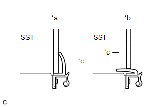
*a
Correct
*b
Incorrect
*c
Outer Lip
- Do not allow foreign matter to attach to the inner lip and outer lip of the front drive shaft oil seal LH.
- Do not install the front drive shaft oil seal LH at an angle.
- Do not remove the grease from the inner lip and outer lip of the front drive shaft oil seal LH.
5. INSTALL FRONT DRIVE SHAFT OIL SEAL RH
(a) Using SST and a hammer, install a new front drive shaft oil seal RH to the continuously variable transaxle assembly.
|
*a |
Inner Lip |
|
*b |
Outer Lip |
SST: 09950-70010
09951-07150
SST: 09316-10010
Standard Depth:
-0.5 to 0.5 mm (-0.0197 to 0.0197 in.)
NOTICE:
- Make sure that the outer lip of the front drive shaft oil seal RH is not
pinched by SST.
*a
Correct
*b
Incorrect
*c
Outer Lip
- Do not allow foreign matter to attach to the inner lip and outer lip of the front drive shaft oil seal RH.
- Do not install the front drive shaft oil seal RH at an angle.
- Do not remove the grease from the inner lip and outer lip of the front drive shaft oil seal RH.
6. INSTALL FRONT DRIVE SHAFT ASSEMBLY
Click here


