Toyota Corolla Cross: Disassembly
DISASSEMBLY
CAUTION / NOTICE / HINT
COMPONENTS (DISASSEMBLY)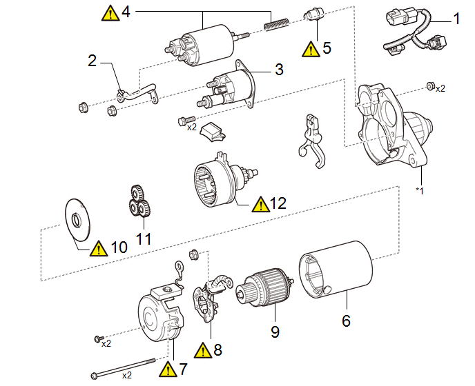
|
Procedure | Part Name Code |
.png) |
.png) |
 |
|---|---|---|---|---|---|
|
1 | HARNESS |
- | - |
- | - |
|
2 | WIRE HARNESS |
- | - |
- | - |
|
3 | STARTER INRUSH CURRENT REDUCTION RELAY |
28249 | - |
- | - |
|
4 | REPAIR SERVICE STARTER KIT |
28226B |
|
- | - |
|
5 | PLUNGER |
- |
|
- | - |
|
6 | STARTER YOKE ASSEMBLY |
28120 | - |
- | - |
|
7 | STARTER COMMUTATOR END FRAME ASSEMBLY |
- |
|
- | - |
|
8 | STARTER BRUSH HOLDER ASSEMBLY |
28140 |
|
- | - |
|
9 | STARTER ARMATURE ASSEMBLY |
28160 | - |
- | - |
|
10 | STARTER ARMATURE PLATE |
- |
|
- | - |
|
11 | PLANETARY GEAR |
- | - |
- | - |
|
12 | STARTER CENTER BEARING CLUTCH SUB-ASSEMBLY |
28021 |
|
- | - |
.gif)
|
*1 | STARTER DRIVE HOUSING ASSEMBLY |
- | - |
PROCEDURE
1. REMOVE HARNESS

2. REMOVE WIRE HARNESS

|
*1 | Wire Harness |
- | - |
|
*a | Nut |
*b | Noise Filter Harness |
3. REMOVE STARTER INRUSH CURRENT REDUCTION RELAY

|
*a | Lead Wire |
- | - |
4. REMOVE SERVICE STARTER KIT

5. REMOVE PLUNGER

|
*1 | Pinion Drive Lever |
*2 | Plunger |
|
*a | Hook |
- | - |
(1) While lifting the rear of the magnet switch, remove the hook from the pinion drive lever, then remove the repair service starter kit.
NOTICE:
Do not drop the plunger when removing the repair service starter kit.
6. REMOVE STARTER YOKE ASSEMBLY

|
*1 | Starter Yoke Assembly |
*2 | Starter Commutator End Frame Assembly |
7. REMOVE STARTER COMMUTATOR END FRAME ASSEMBLY

|
*1 | Starter Yoke Assembly |
*2 | Starter Commutator End Frame Assembly |
|
*a | Lead Wire |
- | - |
(1) Remove the 2 screws.
(2) While holding down the lead wire, remove the starter commutator end frame assembly from the starter yoke assembly.
8. REMOVE STARTER BRUSH HOLDER ASSEMBLY

|
*a | Brush Spring |
*b | Brush |
(1) Using a screwdriver, hold the brush spring back and disconnect the 4 brushes.
(2) Remove the starter brush holder assembly from the starter armature assembly.
9. REMOVE STARTER ARMATURE ASSEMBLY

|
*1 | Starter Yoke Assembly |
*2 | Starter Armature Assembly |
10. REMOVE STARTER ARMATURE PLATE

|
*1 | Starter Yoke Assembly |
*2 | Starter Drive Housing Assembly |
|
*3 | Starter Armature Plate |
- | - |
(1) Remove the starter armature plate from the starter drive housing assembly or starter yoke assembly.
11. REMOVE PLANETARY GEAR

12. REMOVE STARTER CENTER BEARING CLUTCH SUB-ASSEMBLY

|
*1 | Starter Center Bearing Clutch Sub-assembly |
*2 | Pinion Drive Lever |
|
*3 | Rubber Seal |
- | - |
(1) Remove the starter center bearing clutch sub-assembly together with the pinion drive lever and rubber seal from the starter drive housing assembly.
(2) Remove the pinion drive lever and rubber seal from the starter center bearing clutch sub-assembly.


