Toyota Corolla Cross: Back Door Closer does not Operate
DESCRIPTION
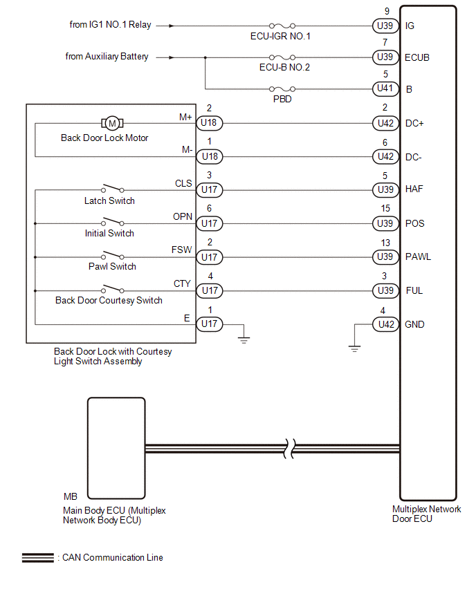
The back door lock with courtesy light switch assembly is controlled by the multiplex network door ECU. The multiplex network door ECU is activated according to the switch signals in the back door lock with courtesy light switch assembly.
WIRING DIAGRAM
CAUTION / NOTICE / HINT
NOTICE:
- Inspect fuses for circuits related to this system before performing the following inspection procedure.
- If the replacement, removal and installation of the multiplex network door ECU or disconnection of the connectors of the multiplex network door ECU has been performed, initialize the power back door system.
Click here
.gif)
PROCEDURE
|
1. | CHECK FOR DTC |
(a) Check for DTCs.
Body Electrical > Back Door > Trouble Codes|
Result | Proceed to |
|---|---|
|
DTC is not output | A |
|
DTC is output | B |
| B |
.gif) | GO TO DIAGNOSTIC TROUBLE CODE CHART
|
|
.gif)
| 2. |
CHECK BACK DOOR LOCK FUNCTION |
(a) Check if the back door can be fully closed by hand.
|
Result | Proceed to |
|---|---|
|
The back door can be closed normally |
A |
| The back door cannot be closed normally |
B |
| B |
| IMPROPER FIT OF BACK DOOR, OR A FOREIGN OBJECT IS STUCK IN BACK DOOR |
|
| 3. |
CHECK HARNESS AND CONNECTOR (MULTIPLEX NETWORK DOOR ECU - BATTERY AND BODY GROUND) |
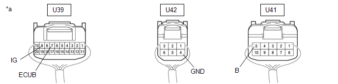
(a) Disconnect the multiplex network door ECU connectors.
|
*a | Rear view of wire harness connector (to Multiplex Network Door ECU) |
- | - |
(b) Measure the resistance according to the value(s) in the table below.
Standard Resistance:
|
Tester Connection | Condition |
Specified Condition |
|---|---|---|
|
U42-4 (GND) - Body ground |
Always | Below 1 Ω |
(c) Measure the voltage according to the value(s) in the table below.
Standard Voltage:
|
Tester Connection | Switch Condition |
Specified Condition |
|---|---|---|
|
U39-7 (ECUB) - Body ground |
Ignition switch off | 11 to 14 V |
|
U41-5 (B) - Body ground |
Ignition switch off | 11 to 14 V |
|
U39-9 (IG) - Body ground |
Ignition switch ON | 11 to 14 V |
|
Ignition switch off | Below 1 V |
| NG | | REPAIR OR REPLACE HARNESS OR CONNECTOR |
|
| 4. |
INSPECT BACK DOOR LOCK WITH COURTESY LIGHT SWITCH ASSEMBLY |
Click here
| NG | | REPLACE BACK DOOR LOCK WITH COURTESY LIGHT SWITCH ASSEMBLY |
|
| 5. |
CHECK HARNESS AND CONNECTOR (BACK DOOR LOCK WITH COURTESY LIGHT SWITCH ASSEMBLY - MULTIPLEX NETWORK DOOR ECU AND BODY GROUND) |
(a) Disconnect the U42 and U39 multiplex network door ECU connectors.
(b) Measure the resistance according to the value(s) in the table below.
Standard Resistance:
|
Tester Connection | Condition |
Specified Condition |
|---|---|---|
|
U18-2 (M+) - U42-2 (DC+) |
Always | Below 1 Ω |
|
U18-1 (M-) - U42-6 (DC-) |
Always | Below 1 Ω |
|
U17-4 (CTY) - U39-3 (FUL) |
Always | Below 1 Ω |
|
U17-2 (FSW) - U39-13 (PAWL) |
Always | Below 1 Ω |
|
U17-3 (CLS) - U39-5 (HAF) |
Always | Below 1 Ω |
|
U17-6 (OPN) - U39-15 (POS) |
Always | Below 1 Ω |
|
U17-1 (E) - Body ground |
Always | Below 1 Ω |
|
U18-2 (M+) or U42-2 (DC+) - Body ground |
Always | 10 kΩ or higher |
|
U18-1 (M-) or U42-6 (DC-) - Body ground |
Always | 10 kΩ or higher |
|
U17-2 (FSW) or U39-13 (PAWL) - Body ground |
Always | 10 kΩ or higher |
|
U17-4 (CTY) or U39-3 (FUL) - Body ground |
Always | 10 kΩ or higher |
|
U17-3 (CLS) or U39-5 (HAF) - Body ground |
Always | 10 kΩ or higher |
|
U17-6 (OPN) or U39-15 (POS) - Body ground |
Always | 10 kΩ or higher |
| OK | | REPLACE MULTIPLEX NETWORK DOOR ECU |
| NG | | REPAIR OR REPLACE HARNESS OR CONNECTOR |


