Toyota Corolla Cross: Wireless Charger Assembly
Removal
REMOVAL
CAUTION / NOTICE / HINT
COMPONENTS (REMOVAL)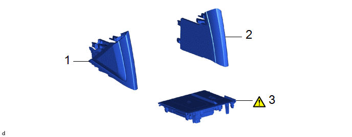
|
Procedure | Part Name Code |
.png) |
.png) |
 |
|---|---|---|---|---|---|
|
1 | NO. 2 CONSOLE UPPER PANEL GARNISH |
58834B | - |
- | - |
|
2 | NO. 1 CONSOLE UPPER PANEL GARNISH |
58833B | - |
- | - |
|
3 | MOBILE WIRELESS CHARGER CRADLE ASSEMBLY |
861C0 |
|
- | - |
PROCEDURE
1. REMOVE NO. 2 CONSOLE UPPER PANEL GARNISH
Click here
.gif)
2. REMOVE NO. 1 CONSOLE UPPER PANEL GARNISH
(a) Use the same procedure as for the No. 2 console upper panel garnish.
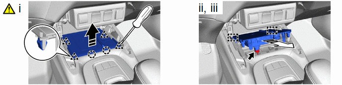
3. REMOVE MOBILE WIRELESS CHARGER CRADLE ASSEMBLY
.png) |
Separate in this Direction |
.png) |
Remove in this Direction |
(1) Using a screwdriver with its tip wrapped with protective tape, disengage the clips and claws to separate the mobile wireless charger cradle assembly as shown in the illustration.
(2) Disconnect the connector.
(3) Disengage the guides to remove the mobile wireless charger cradle assembly.
Installation
INSTALLATION
CAUTION / NOTICE / HINT
COMPONENTS (INSTALLATION)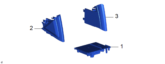
|
Procedure | Part Name Code |
.png) |
.png) |
 |
|---|---|---|---|---|---|
|
1 | MOBILE WIRELESS CHARGER CRADLE ASSEMBLY |
861C0 | - |
- | - |
|
2 | NO. 2 CONSOLE UPPER PANEL GARNISH |
58834B | - |
- | - |
|
3 | NO. 1 CONSOLE UPPER PANEL GARNISH |
58833B | - |
- | - |
PROCEDURE
1. INSTALL MOBILE WIRELESS CHARGER CRADLE ASSEMBLY
2. INSTALL NO. 2 CONSOLE UPPER PANEL GARNISH
3. INSTALL NO. 1 CONSOLE UPPER PANEL GARNISH


