Toyota Corolla Cross: There is No Sound Made
DESCRIPTION
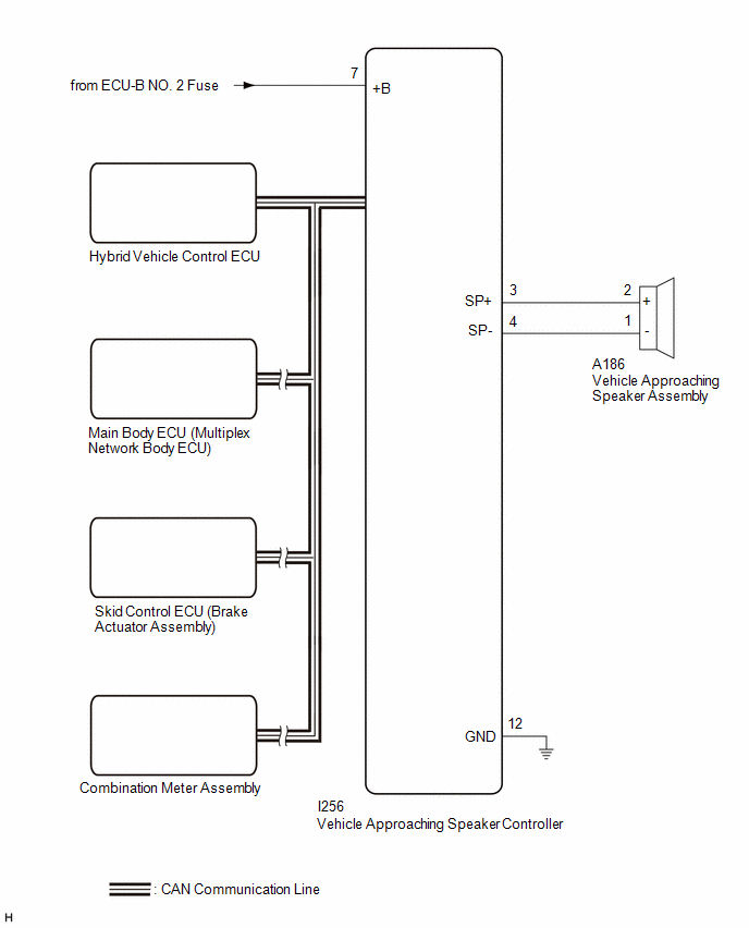
Based on signals received from each ECU, the vehicle approaching speaker controller outputs warning sounds through the vehicle approaching speaker assembly.
WIRING DIAGRAM
CAUTION / NOTICE / HINT
NOTICE:
- Inspect the fuses for circuits related to this system before performing the following procedure.
- The acoustic vehicle alerting system uses the CAN communication system. Inspect the communication functions by following How to Proceed with Troubleshooting.
Click here
.gif)
PROCEDURE
|
1. | CHECK FOR DTC |
(a) Check for DTCs.
Body Electrical > Acoustic Vehicle Alerting System > Trouble Codes|
Result | Proceed to |
|---|---|
|
B135013 and B135019 are not output |
A |
| B135013 and B135019 is output |
B |
| B |
.gif) | GO TO DTC CHART |
|
.gif)
| 2. |
PERFORM ACTIVE TEST USING GTS |
(a) Perform the Active Test according to the display on the GTS.
Body Electrical > Acoustic Vehicle Alerting System > Active Test|
Tester Display | Measurement Item |
Control Range | Diagnostic Note |
|---|---|---|---|
|
Proximity Sound (20km/h,12MPH) |
20 km/h (12 mph) vehicle proximity warning sound |
OFF or ON | - |
|
Tester Display |
|---|
| Proximity Sound (20km/h,12MPH) |
|
Result | Proceed to |
|---|---|
|
The warning sound is produced |
A |
| The warning sound is not produced |
B |
| A |
| REPLACE VEHICLE APPROACHING SPEAKER CONTROLLER |
|
| 3. |
CHECK HARNESS AND CONNECTOR (VEHICLE APPROACHING SPEAKER CONTROLLER - POWER SOURCE AND BODY GROUND) |
(a) Disconnect the I256 vehicle approaching speaker controller connector.
(b) Measure the voltage according to the value(s) in the table below.
Standard Voltage:
|
Tester Connection | Condition |
Specified Condition |
|---|---|---|
|
I256-7 (+B) - Body ground |
Ignition switch off | 11 to 14 V |
(c) Measure the resistance according to the value(s) in the table below.
Standard Resistance:
|
Tester Connection | Condition |
Specified Condition |
|---|---|---|
|
I256-12 (GND) - Body ground |
Always | Below 1 Ω |
| OK | | REPLACE VEHICLE APPROACHING SPEAKER CONTROLLER |
| NG | | REPAIR OR REPLACE HARNESS OR CONNECTOR |


