Toyota Corolla Cross: System Diagram
SYSTEM DIAGRAM
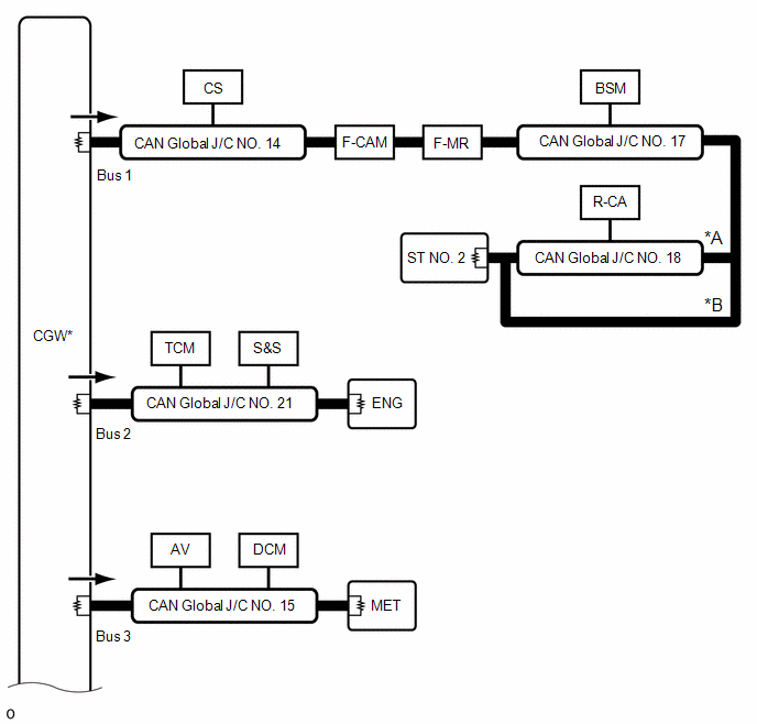
OVERALL CAN BUS DIAGRAM
|
*A |
w/ Parking Assist Monitor System |
*B |
w/o Parking Assist Monitor System |
 |
CAN Main Bus Line |
 |
Terminating Resistor |
 |
CAN Branch Line |
* |
Gateway Function Equipped ECU |
 |
Bus Monitoring Direction |
- |
- |
|
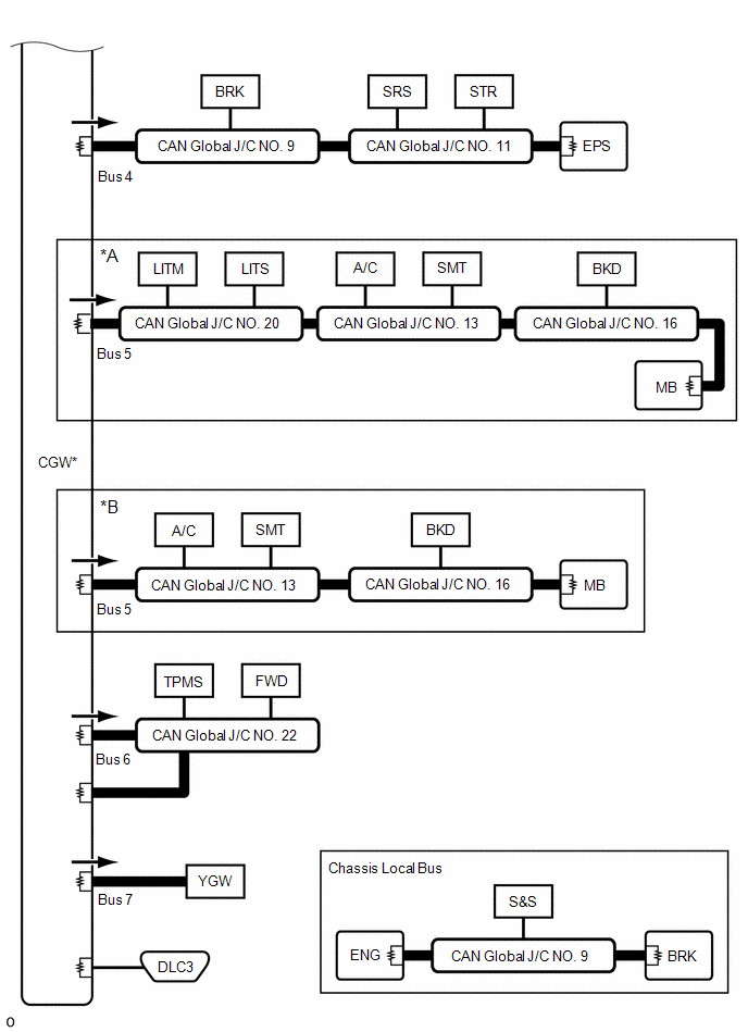
*A |
w/ AFS |
*B |
w/o AFS |
|
|
CAN Main Bus Line |
|
Terminating Resistor |
|
|
CAN Branch Line |
* |
Gateway Function Equipped ECU |
|
|
Bus Monitoring Direction |
- |
- |
|
Connected to |
Code |
ECU/Sensor Name |
GTS Display |
Applicability |
|---|---|---|---|---|
|
- |
CGW |
Central Gateway ECU (Network Gateway ECU) |
- |
Installed on all vehicles |
|
- |
DLC3 |
DLC3 |
- |
Installed on all vehicles |
|
Bus 1 |
CS |
Clearance Warning ECU Assembly |
Clearance Warning (Intuitive Parking Assist) |
w/ Intuitive Parking Assist System |
|
F-CAM |
Forward Recognition Camera |
Front Camera Module |
Installed on all vehicles |
|
|
F-MR |
Millimeter Wave Radar Sensor Assembly |
Front Radar |
Installed on all vehicles |
|
|
BSM |
Blind Spot Monitor Sensor LH (B) |
Blind Spot Monitor "B" |
w/ Blind Spot Monitor System |
|
|
R-CA |
Rear Television Camera Assembly |
Parking Assist Monitor System / Rear Camera |
w/ Parking Assist Monitor System |
|
|
CAN Global J/C NO. 14 |
No. 14 Global CAN Junction Connector |
- |
Installed on all vehicles |
|
|
CAN Global J/C NO. 17 |
No. 17 Global CAN Junction Connector |
- |
Installed on all vehicles |
|
|
CAN Global J/C NO. 18 |
No. 18 Global CAN Junction Connector |
- |
w/ Parking Assist Monitor System |
|
|
ST NO. 2 |
No. 2 CAN Junction Terminal |
- |
Installed on all vehicles |
|
|
Bus 2 |
TCM |
TCM |
TCM |
Installed on all vehicles |
|
S&S |
Engine Stop and Start ECU |
Stop and Go/Start |
Installed on all vehicles |
|
|
ENG |
ECM |
ECM (Engine) |
Installed on all vehicles |
|
|
CAN Global J/C NO. 21 |
No. 21 Global CAN Junction Connector |
- |
Installed on all vehicles |
|
|
Bus 3 |
AV |
Radio and Display Receiver Assembly |
Display and Navigation (AVN) |
Installed on all vehicles |
|
DCM |
DCM (Telematics Transceiver) |
DCM |
w/ Telematics Transceiver |
|
|
MET |
Combination Meter Assembly |
Combination Meter |
Installed on all vehicles |
|
|
CAN Global J/C NO. 15 |
No. 15 Global CAN Junction Connector |
- |
Installed on all vehicles |
|
|
Bus 4 |
BRK |
Brake Actuator Assembly |
Skid Control (ABS/VSC/TRAC) |
Installed on all vehicles |
|
SRS |
Airbag ECU Assembly |
Airbag |
Installed on all vehicles |
|
|
STR |
Steering Sensor |
Spiral Cable (Steering Angle Sensor) |
Installed on all vehicles |
|
|
EPS |
Power Steering ECU Assembly |
Power Steering (EPS) |
Installed on all vehicles |
|
|
CAN Global J/C NO. 9 |
No. 9 Global CAN Junction Connector |
- |
Installed on all vehicles |
|
|
CAN Global J/C NO. 11 |
No. 11 Global CAN Junction Connector |
- |
Installed on all vehicles |
|
|
Bus 5 |
LITM |
Headlight ECU Sub-assembly LH |
Headlight Control |
w/ AFS |
|
LITS |
Headlight ECU Sub-assembly RH |
Headlight Control (Sub) |
w/ AFS |
|
|
A/C |
Air Conditioning Amplifier Assembly |
Air Conditioning Amplifier |
Installed on all vehicles |
|
|
SMT |
Certification ECU (Smart Key ECU Assembly) |
|
w/ Smart Key System |
|
|
BKD |
Multiplex Network Door ECU |
Back Door |
w/ Power Back Door |
|
|
MB |
Main Body ECU (Multiplex Network Body ECU) |
Main Body |
Installed on all vehicles |
|
|
CAN Global J/C NO. 13 |
No. 13 Global CAN Junction Connector |
- |
Installed on all vehicles |
|
|
CAN Global J/C NO. 16 |
No. 16 Global CAN Junction Connector |
- |
Installed on all vehicles |
|
|
CAN Global J/C NO. 20 |
No. 20 Global CAN Junction Connector |
- |
w/ AFS |
|
|
Bus 6 |
TPMS |
Tire Pressure Warning ECU and Receiver |
Tire Pressure |
Installed on all vehicles |
|
FWD |
4WD ECU Assembly |
Four Wheel Drive Control |
for AWD |
|
|
CAN Global J/C NO. 22 |
No. 22 Global CAN Junction Connector |
- |
Installed on all vehicles |
|
|
Bus 7 |
YGW |
Option Connector (Bus Buffer ECU) |
Accessory Gateway |
Installed on all vehicles |
|
Chassis Local Bus |
BRK |
Brake Actuator Assembly |
- |
Installed on all vehicles |
|
S&S |
Engine Stop and Start ECU |
- |
Installed on all vehicles |
|
|
ENG |
ECM |
- |
Installed on all vehicles |
|
|
CAN Global J/C NO. 9 |
No. 9 Global CAN Junction Connector |
- |
Installed on all vehicles |


