Toyota Corolla Cross: System Diagram
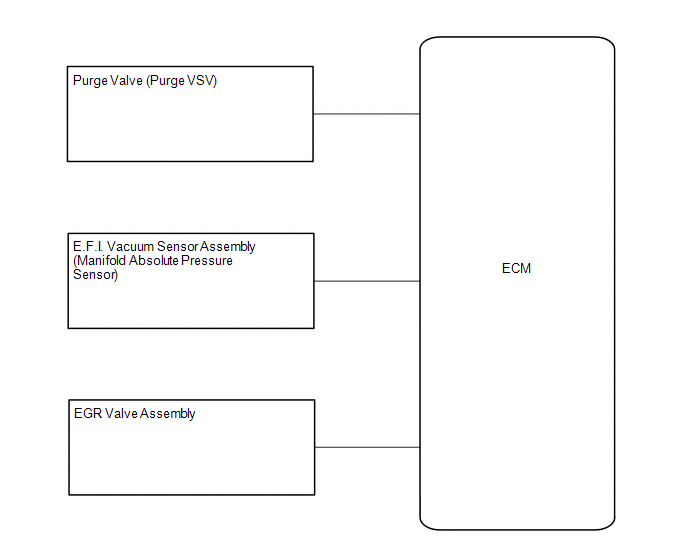
SYSTEM DIAGRAM
READ NEXT:
ON-VEHICLE INSPECTION CAUTION / NOTICE / HINT
CAUTION:
When working near the engine room while the engine has started or the power source mode is ignition switch to ON, do not touch the fan and
InspectionINSPECTION PROCEDURE
1. INSPECT FUEL TANK CAP ASSEMBLY
(a) Visually check that the fuel tank cap assembly and gasket are not deformed or damaged.
If the fuel tank cap assembly or
On-vehicle InspectionON-VEHICLE INSPECTION PROCEDURE
1. INSPECT PCV VALVE (VENTILATION VALVE SUB-ASSEMBLY)
(a) Check the PCV valve (ventilation valve sub-assembly) operation.
(1) Start the
SEE MORE:
DIAGNOSIS SYSTEM
PARKING ASSIST MONITOR SYSTEM DIAGNOSTIC MODE
(a) In diagnostic mode for the parking assist monitor system, signals
received by the radio and display receiver assembly can be checked and the parking
assist monitor system can be calibrated, adjusted and checked using the radio
DESCRIPTION The BIN resistance is equipped for the purpose of correcting variances in brightness (luminous flux) when the headlight ECU sub-assembly is energizing the LED with a constant current to illuminate it.
Also, it monitors the voltage applied to the BIN resistance in order to detect abnorma
 On-vehicle Inspection
 Diagnosis System
