Toyota Corolla Cross: Sound cannot be Heard Sound Quality is Poor only when Replaying USB Storage Device or "iPod"
WIRING DIAGRAM

CAUTION / NOTICE / HINT
NOTICE:
Depending on the parts that are replaced during vehicle inspection or maintenance, performing initialization, registration or calibration may be needed.
Click here .gif)
PROCEDURE
|
1. |
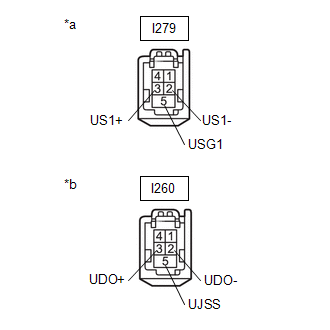
CHECK HARNESS AND CONNECTOR (RADIO AND DISPLAY RECEIVER ASSEMBLY - STEREO JACK ADAPTER ASSEMBLY) |
(a) Disconnect the I279 radio and display receiver assembly connector.
(b) Disconnect the I260 stereo jack adapter assembly connector.
|
(c) Measure the resistance according to the value(s) in the table below. Standard Resistance:
|
|
| NG | .gif)
|
REPAIR OR REPLACE HARNESS OR CONNECTOR |
|
.gif)
|
2. |
CHECK STEREO JACK ADAPTER ASSEMBLY |
(a) Replace the stereo jack adapter assembly with a new or known good one.
Click here
(b) Check if the problem symptom recurs.
|
Result |
Proceed to |
|---|---|
|
Malfunction disappears |
A |
|
Malfunction occurs |
B |
| A |
|
END (STEREO JACK ADAPTER ASSEMBLY MALFUNCTIO) |
| B |
|
REPLACE RADIO AND DISPLAY RECEIVER ASSEMBLY |
READ NEXT:
 Even though Headlights are Turned on Head-unit does not Dim the Display
WIRING DIAGRAM
CAUTION / NOTICE / HINT
NOTICE:
Depending on the parts that are replaced during vehicle inspection
or maintenance, performing initialization, registration or calibration may be n
Removal
REMOVAL
CAUTION / NOTICE / HINT
COMPONENTS (REMOVAL)
Procedure
Part Name Code
1
FRONT DOOR INSIDE HANDLE BEZEL PLUG
SEE MORE:
 How To Proceed With Troubleshooting
PROCEDURE
1.
VEHICLE BROUGHT TO WORKSHOP
NEXT
2.
CONFIRM PROBLEM SYMPTOMS
NEXT
3.
Lost Communication with Front Control Rear Air Outlet Damper Control Servo Motor LIN Missing Message (B13AA87)
DESCRIPTION The air conditioning harness assembly connects the air conditioning amplifier assembly and No. 2 air conditioning radiator damper servo sub-assembly.
The No. 2 air conditioning radiator damper servo sub-assembly sends damper position information to the air conditioning amplifier assemb
