Toyota Corolla Cross: Removal
REMOVAL
CAUTION / NOTICE / HINT
COMPONENTS (REMOVAL)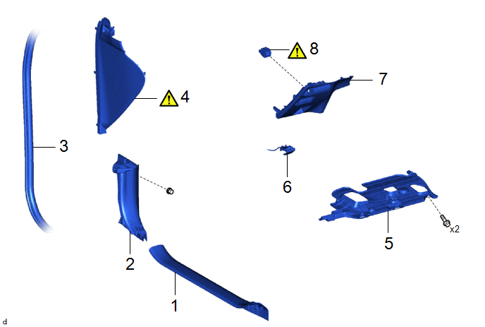
|
Procedure | Part Name Code |
.png) |
.png) |
 |
|---|---|---|---|---|---|
|
1 | FRONT DOOR SCUFF PLATE LH |
67914B | - |
- | - |
|
2 | COWL SIDE TRIM SUB-ASSEMBLY LH |
62112A | - |
- | - |
|
3 | FRONT DOOR OPENING TRIM WEATHERSTRIP LH |
62312B | - |
- | - |
|
4 | NO. 1 INSTRUMENT SIDE PANEL |
55317E |
|
- | - |
|
5 | NO. 1 INSTRUMENT PANEL UNDER COVER SUB-ASSEMBLY |
55606 | - |
- | - |
|
6 | HOOD LOCK CONTROL LEVER SUB-ASSEMBLY |
53601 | - |
- | - |
|
7 | LOWER NO. 1 INSTRUMENT PANEL FINISH PANEL |
55432D | - |
- | - |
|
8 | LIGHT CONTROL RHEOSTAT |
84119 |
|
- | - |
PROCEDURE
1. REMOVE FRONT DOOR SCUFF PLATE LH
Click here
.gif)
2. REMOVE COWL SIDE TRIM SUB-ASSEMBLY LH
Click here
3. DISCONNECT FRONT DOOR OPENING TRIM WEATHERSTRIP LH
Click here
4. REMOVE NO. 1 INSTRUMENT SIDE PANEL
|
|
Click here |
5. REMOVE NO. 1 INSTRUMENT PANEL UNDER COVER SUB-ASSEMBLY
Click here
6. DISCONNECT HOOD LOCK CONTROL LEVER SUB-ASSEMBLY
Click here
7. REMOVE LOWER NO. 1 INSTRUMENT PANEL FINISH PANEL
Click here
8. REMOVE LIGHT CONTROL RHEOSTAT
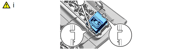
(1) Using a screwdriver with its tip wrapped with protective tape, disengage the claws to remove the light control rheostat.


