Toyota Corolla Cross: Inspection
INSPECTION
PROCEDURE
1. INSPECT LIGHT CONTROL RHEOSTAT
(a) Check the resistance.
| (1) Measure the resistance according to the value(s) in the table below.
Standard Resistance: |
Tester Connection | Condition |
Specified Condition | |
I228-4 (RV) - I228-2 (E) |
Light control rheostat knob fully downwards (MIN.) |
Below 50 Ω | |
I228-4 (RV) - I228-2 (E) |
Light control rheostat knob between MIN. and MAX. |
The value changes gradually (Between 0 to 12 kΩ) | |
I228-4 (RV) - I228-2 (E) |
Light control rheostat knob fully upwards (MAX.) |
8 to 12 kΩ | |
I228-3 (TC) - I228-2 (E) |
Light control rheostat knob not fully upward |
8 to 12 kΩ | |
I228-3 (TC) - I228-2 (E) |
Light control rheostat knob fully upwards (Tail cancel switch is on) |
1 MΩ or higher | If the result is not as specified, replace the light control rheostat. |
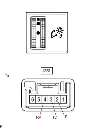 |
|
*a | Component without harness connected
(Light Control Rheostat) | | |
(b) Check the illumination.
| (1) Apply auxiliary battery voltage to the light control rheostat and check that it illuminates.
OK: |
Tester Connection | Specified Condition | |
I228-6 (ILL+) - Auxiliary battery positive (+) I228-1 (ILL-) - Auxiliary battery negative (-) |
Illuminates | If the result is not as specified, replace the light control rheostat. |
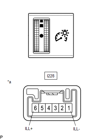 |
|
*a | Component without harness connected
(Light Control Rheostat) | | |
READ NEXT:
INSTALLATION CAUTION / NOTICE / HINT COMPONENTS (INSTALLATION)
Procedure Part Name Code
1 LIGHT CONTROL RHEOSTAT
84119 -
- -
2 LOWER NO
PRECAUTION PRECAUTION FOR DISCONNECTING CABLE FROM NEGATIVE (-) AUXILIARY BATTERY TERMINAL
NOTICE:
After the ignition switch is turned off, there may be a waiting time before disconnecting the n
SEE MORE:
INSTALLATION CAUTION / NOTICE / HINT COMPONENTS (INSTALLATION)
Procedure Part Name Code
1 FUEL MAIN VALVE ASSEMBLY
23070
- -
2 FUEL PRESSURE REGULATOR HOLDER
23283B -
- -
3 FUEL SUCTION TUBE WITH PUMP A
DATA LIST / ACTIVE TEST
NOTICE:
In the table below, the values listed under "Normal Condition" are reference values. Do not depend solely on these reference values when deciding whether a part is faulty or not.
When using the GTS with the ignition switch off, connect the GTS to the DLC3 a



