Toyota Corolla Cross: Removal
REMOVAL
CAUTION / NOTICE / HINT
COMPONENTS (REMOVAL)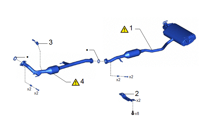
|
Procedure | Part Name Code |
.png) |
.png) |
 |
|---|---|---|---|---|---|
|
1 | TAIL EXHAUST PIPE ASSEMBLY |
17430 |
|
- | - |
|
2 | FRONT FLOOR CENTER BRACE |
57533B | - |
- | - |
|
3 | AIR FUEL RATIO SENSOR |
89467C | - |
- | - |
|
4 | FRONT EXHAUST PIPE ASSEMBLY (TWC: Rear Catalyst) |
17410 |
|
- | - |
|
● | Non-reusable part |
- | - |
CAUTION / NOTICE / HINT
The necessary procedures (adjustment, calibration, initialization or registration) that must be performed after parts are removed and installed, or replaced during front exhaust pipe assembly (TWC: Rear Catalyst) and tail exhaust pipe assembly removal/installation are shown below.
Necessary Procedures After Parts Removed/Installed/Replaced|
Replaced Part or Performed Procedure |
Necessary Procedure | Effect/Inoperative Function when Necessary Procedure not Performed |
Link |
|---|---|---|---|
| Inspection after repair |
|
|
CAUTION:
To prevent burns, do not touch the engine, exhaust pipe or other high temperature components while the engine is hot.
.png)
PROCEDURE
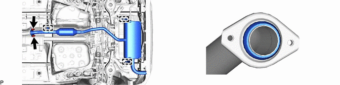
1. REMOVE TAIL EXHAUST PIPE ASSEMBLY
|
|
CAUTION: To prevent burns, do not touch the engine, exhaust pipe or other high temperature components while the engine is hot. |
2. REMOVE FRONT FLOOR CENTER BRACE
Click here .gif)
3. REMOVE AIR FUEL RATIO SENSOR
Click here
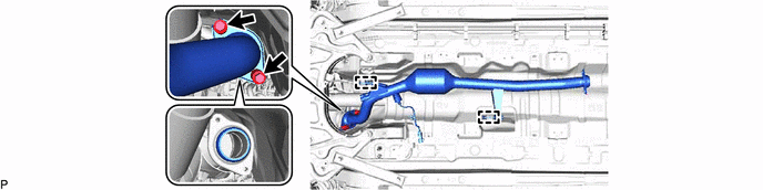
4. REMOVE FRONT EXHAUST PIPE ASSEMBLY (TWC: Rear Catalyst)
|
|
CAUTION: To prevent burns, do not touch the engine, exhaust pipe or other high temperature components while the engine is hot. |