Toyota Corolla Cross: Removal
REMOVAL
CAUTION / NOTICE / HINT
COMPONENTS (REMOVAL)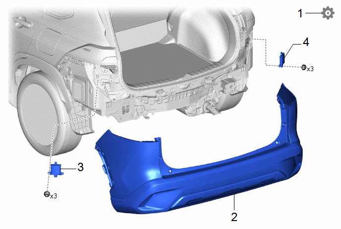
|
Procedure |
Part Name Code |
.png) |
.png) |
.png) |
|
|---|---|---|---|---|---|
|
1 |
BSM ECU DATE SAVE |
- |
- |
- |
|
|
2 |
REAR BUMPER ASSEMBLY |
- |
- |
- |
- |
|
3 |
BLIND SPOT MONITOR SENSOR LH |
88172 |
- |
- |
- |
|
4 |
BLIND SPOT MONITOR SENSOR RH |
88162 |
- |
- |
- |
CAUTION / NOTICE / HINT
The necessary procedures (adjustment, calibration, initialization, or registration) that must be performed after parts are removed and installed, or replaced during the blind spot monitor sensor removal/installation are shown below.
Necessary Procedure After Parts Removed/Installed/Replaced|
Replaced Part or Performed Procedure |
Necessary Procedure |
Effect/Inoperative Function when Necessary Procedure not Performed |
Link |
|---|---|---|---|
|
Blind spot monitor sensor |
Blind spot monitor beam axis adjustment |
|
|
NOTICE:
- Avoid any impact to the blind spot monitor sensor.
- Do not drop the blind spot monitor sensor. If it is dropped, replace it with a new one.
PROCEDURE
1. BSM ECU DATE SAVE
Click here .gif)
2. REMOVE REAR BUMPER ASSEMBLY
- except Sport Package:
Click here
- for Sport Package:
Click here
3. REMOVE BLIND SPOT MONITOR SENSOR LH

4. REMOVE BLIND SPOT MONITOR SENSOR RH
(a) Use the same procedure as for the LH side.


