Toyota Corolla Cross: Installation
INSTALLATION
CAUTION / NOTICE / HINT
COMPONENTS (INSTALLATION)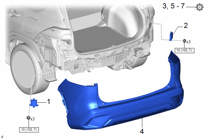
|
Procedure |
Part Name Code |
.png) |
.png) |
.png) |
|
|---|---|---|---|---|---|
|
1 |
BLIND SPOT MONITOR SENSOR LH |
88172 |
- |
- |
- |
|
2 |
BLIND SPOT MONITOR SENSOR RH |
88162 |
- |
- |
- |
|
3 |
PERFORM BLIND SPOT MONITOR SENSOR INSTALLATION CONDITION INSPECTION |
- |
- |
- |
|
|
4 |
REAR BUMPER ASSEMBLY |
- |
- |
- |
- |
|
5 |
BSM ECU DATE WRITE |
- |
- |
- |
|
|
6 |
PERFORM BLIND SPOT MONITOR BEAM AXIS CONFIRMATION |
- |
- |
- |
|
|
7 |
PERFORM DIAGNOSTIC SYSTEM CHECK |
- |
- |
- |
|
CAUTION / NOTICE / HINT
NOTICE:
- Avoid any impact to the blind spot monitor sensor.
- Do not drop the blind spot monitor sensor. If it is dropped, replace it with a new one.
HINT:
- The blind spot monitor beam axis inspection is performed to confirm whether the sensor is transmitting radio waves.
- The blind spot monitor beam axis confirmation is performed to confirm whether the sensor's beam axis is correct, and perform adjustment of the beam axis by using reflector.
- The blind spot monitor sensor installation condition inspection is performed to confirm whether the sensor is placed vertically to the ground (+/-5°) by using a jig, and that the sensor is 16 to 24° from the line parallel to the vehicle center line.
PROCEDURE
1. INSTALL BLIND SPOT MONITOR SENSOR LH
Torque:
10 N·m {102 kgf·cm, 7 ft·lbf}
2. INSTALL BLIND SPOT MONITOR SENSOR RH
3. PERFORM BLIND SPOT MONITOR SENSOR INSTALLATION CONDITION INSPECTION
Click here .gif)
4. INSTALL REAR BUMPER ASSEMBLY
- except Sport Package:
Click here
- for Sport Package:
Click here
5. BSM ECU DATE WRITE
NOTICE:
BSM ECU data write can only be performed when the beam axis adjustment value is able to be saved to the GTS.
Click here
6. PERFORM BLIND SPOT MONITOR BEAM AXIS CONFIRMATION
NOTICE:
When BSM ECU data write can be performed, it is possible to omit the blind spot monitor beam axis confirmation.
Click here
7. PERFORM DIAGNOSTIC SYSTEM CHECK
Click here


