Toyota Corolla Cross: Parts Location
PARTS LOCATION
ILLUSTRATION
ILLUSTRATION
|
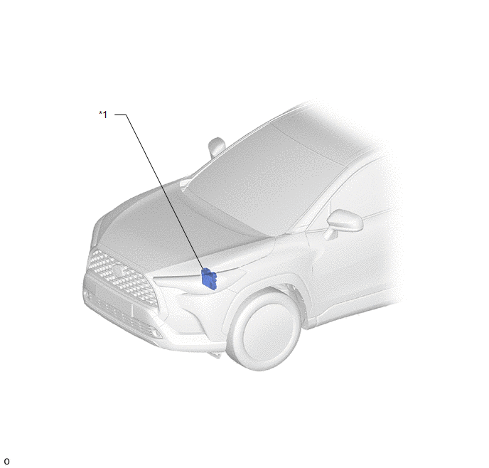
*1 | UNLOCK WARNING SWITCH ASSEMBLY |
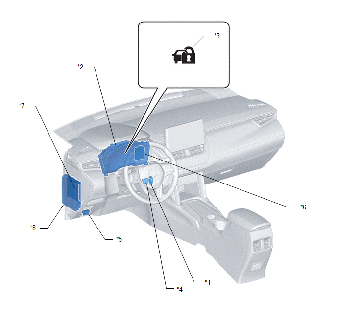
*2 | COMBINATION METER ASSEMBLY |
|
*3 | SECURITY INDICATOR LIGHT |
*4 | TRANSPONDER KEY COIL |
|
*5 | DLC3 |
*6 | TRANSPONDER KEY ECU ASSEMBLY |
|
*7 | MAIN BODY ECU (MULTIPLEX NETWORK BODY ECU) |
*8 | POWER DISTRIBUTION BOX ASSEMBLY |
READ NEXT:
SYSTEM DESCRIPTION IMMOBILISER SYSTEM DESCRIPTION
The immobiliser system is designed to prevent the vehicle from being stolen. This system uses the transponder key ECU assembly that stores the key I
CAUTION / NOTICE / HINT
HINT:
Use the following procedure to troubleshoot the immobiliser system.
*: Use the GTS.
PROCEDURE
1. VEHICLE BROUGHT TO WORKSHOP
NEXT
SEE MORE:
DESCRIPTION
Detection Item
Symptom
Trouble Area
Center Airbag Sensor Communication Stop Mode
Communication stop for "Airbag" is indicated on the "Communication Bus
Check" screen of the GTS.
Click here
RemovalREMOVAL CAUTION / NOTICE / HINT COMPONENTS (REMOVAL)
Procedure Part Name Code
1 NO. 2 FRONT DOOR WEATHERSTRIP
67864F -
- - CAUTION / NOTICE / HINT
HINT:
Use the same procedure for the RH side and LH side.
The following procedure is for th


