Toyota Corolla Cross: Parts Location
PARTS LOCATION
ILLUSTRATION
|
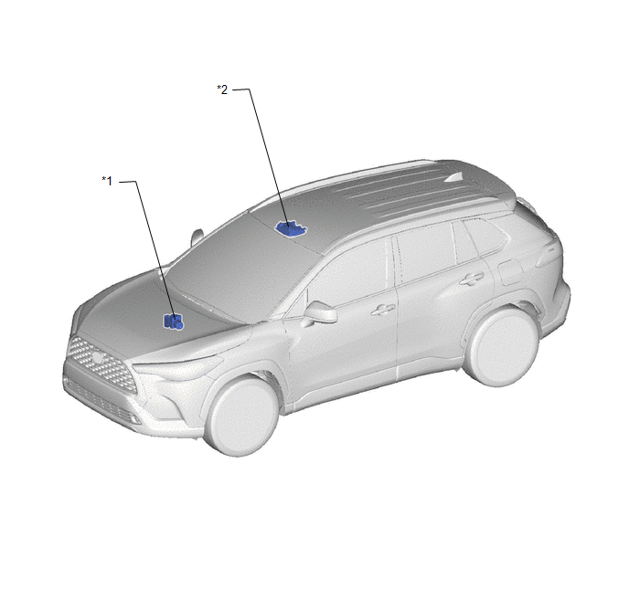
*1 | BRAKE ACTUATOR ASSEMBLY
- SKID CONTROL ECU | *2 |
MAP LIGHT ASSEMBLY - PASSENGER AIRBAG ON/OFF INDICATOR |
ILLUSTRATION
|
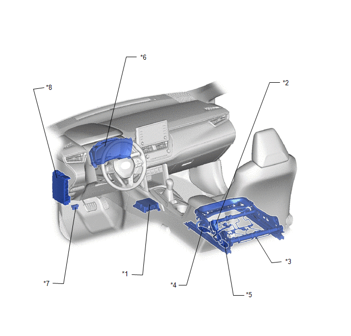
*1 | AIRBAG ECU ASSEMBLY |
*2 | FRONT SEAT INNER BELT ASSEMBLY RH
- PASSENGER SEAT BUCKLE SWITCH |
|
*3 | FRONT SEAT CUSHION SPLING SUB-ASSEMBLY |
*4 | FRONT OCCUPANT CLASSIFICATION SENSOR LH |
|
*5 | REAR OCCUPANT CLASSIFICATION SENSOR LH |
*6 | COMBINATION METER ASSEMBLY
- SRS WARNING LIGHT |
|
*7 | DLC3 |
*8 | POWER DISTRIBUTION BOX ASSEMBLY
- A/BAG-IGR FUSE |
READ NEXT:
SYSTEM DIAGRAM
Communication Table
Transmitting ECU / Parts (Transmitter)
Receiving ECU (Receiver)
Signal Communication Method
Passenger Seat Buckle Switch (Front Seat Inn
SYSTEM DESCRIPTION GENERAL (a) The airbag ECU assembly estimates the weight of an occupant based on signals received from the 2 occupant classification sensors. The airbag ECU assembly determines whet
CAUTION / NOTICE / HINT
HINT:
Use the following procedure to troubleshoot the occupant classification system.
*: Use the GTS.
PROCEDURE
1. VEHICLE BROUGHT TO WORKSHOP
SEE MORE:
INSTALLATION
CAUTION / NOTICE / HINT
COMPONENTS (INSTALLATION)
Procedure
Part Name Code
1
BRAKE PEDAL PAD
47121
-
-
-
2
STOP LIGHT SWITCH MOUNTING
On-vehicle InspectionON-VEHICLE INSPECTION PROCEDURE
1. INSPECT HEADLIGHT RELAY LH (a) Check the operation of the headlight relay LH.
(1) Measure the resistance according to the value(s) in the table below.
Standard Resistance:
Tester Connection Condition
Specified Condition


