Toyota Corolla Cross: Parts Location
PARTS LOCATION
ILLUSTRATION
|
*1
|
for HEV Model
|
-
|
-
|
|
*3
|
NO. 1 ENGINE ROOM RELAY BLOCK
- INP STD NO. 1
- INP STD NO. 2
- INP STD NO. 3
- D/C CUT
|
-
|
-
|
ILLUSTRATION

|
*A
|
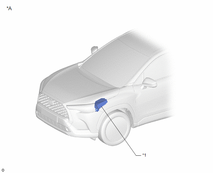
for Gasoline Model
|
-
|
-
|
|
*1
|
NO. 1 ENGINE ROOM RELAY BLOCK
- INP STD NO. 2
- INP STD NO. 3
- D/C CUT
|
*2
|
FUSIBLE LINK BLOCK ASSEMBLY
- INP STD NO. 3
|
ILLUSTRATION
|
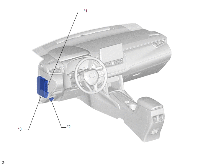
*1
|
MAIN BODY ECU (MULTIPLEX NETWORK BODY ECU)
|
*2
|
DLC3
|
|
*3
|
POWER DISTRIBUTION BOX ASSEMBLY
|
-
|
-
|
READ NEXT:
SYSTEM DESCRIPTION
LOAD OPERATION OUTPUT
(a) Load is turned on or off according to the operation signals and switch signals
from each ECU.
Components
Power Distribution Box
CAUTION / NOTICE / HINT
HINT:
Use these procedures to troubleshoot the power integration system.
*: Use the GTS.
PROCEDURE
1.
VEHICLE BROUGHT TO WORKSHOP
SEE MORE:
INSPECTION PROCEDURE 1. INSPECT WINDSHIELD WASHER MOTOR AND PUMP ASSEMBLY
HINT: This check should be performed with the windshield washer motor and pump assembly installed to the windshield washer jar assembly.
(a) Fill the windshield washer jar assembly with washer fluid.
(b) Check that wash
DESCRIPTION Refer to DTC P003612. Click here
HINT: Although the DTC title say O2 sensor, this DTC relate to the air fuel ratio sensor (sensor 2).
DTC No. Detection Item
DTC Detection Condition Trouble Area
MIL Note
P013616 A/F (O2) Sensor Circuit Bank 1 Sensor 2 C


