Toyota Corolla Cross: Parts Location
PARTS LOCATION
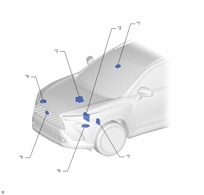
ILLUSTRATION
|
*1 |
FORWARD RECOGNITION CAMERA |
*2 |
ECM |
|
*3 |
BRAKE ACTUATOR ASSEMBLY |
*4 |
HEADLAMP ECU SUB-ASSEMBLY RH (w/ AFS) |
|
*5 |
MILLIMETER WAVE RADAR SENSOR ASSEMBLY |
*6 |
HEADLAMP ECU SUB-ASSEMBLY LH (w/ AFS) |
|
*7 |
TCM |
- |
- |
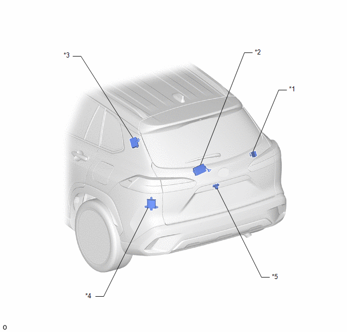
ILLUSTRATION
|
*1 |
4WD ECU ASSEMBLY (for AWD) |
*2 |
MULTIPLEX NETWORK DOOR ECU (w/ Power Back Door) |
|
*3 |
TIRE PRESSURE WARNING ECU AND RECEIVER |
*4 |
BLIND SPOT MONITOR SENSOR LH (B) (w/ Blind Spot Monitor System) |
|
*5 |
REAR TELEVISION CAMERA ASSEMBLY (w/ Parking Assist Monitor System) |
- |
- |
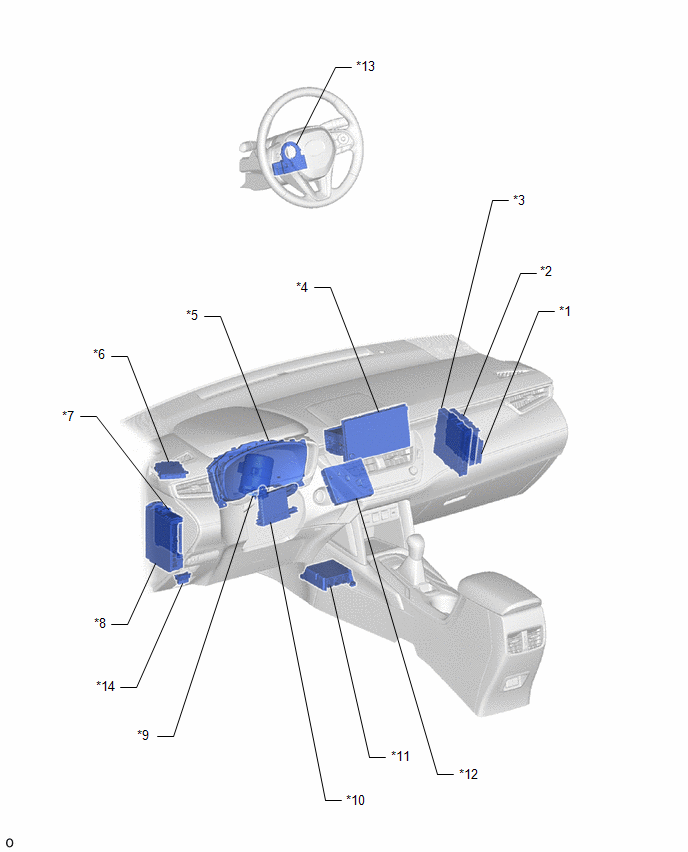
ILLUSTRATION
|
*1 |
CENTRAL GATEWAY ECU (NETWORK GATEWAY ECU) |
*2 |
CERTIFICATION ECU (SMART KEY ECU ASSEMBLY) (w/ Smart Key System) |
|
*3 |
ENGINE STOP AND START ECU |
*4 |
RADIO AND DISPLAY RECEIVER ASSEMBLY |
|
*5 |
COMBINATION METER ASSEMBLY |
*6 |
CLEARANCE WARNING ECU ASSEMBLY (w/ Intuitive Parking Assist System) |
|
*7 |
MAIN BODY ECU (MULTIPLEX NETWORK BODY ECU) |
*8 |
POWER DISTRIBUTION BOX ASSEMBLY |
|
*9 |
POWER STEERING ECU ASSEMBLY |
*10 |
AIR CONDITIONING AMPLIFIER |
|
*11 |
AIRBAG ECU ASSEMBLY |
*12 |
DCM (TELEMATICS TRANSCEIVER) (w/ Telematics Transceiver) |
|
*13 |
STEERING SENSOR |
*14 |
DLC3 |
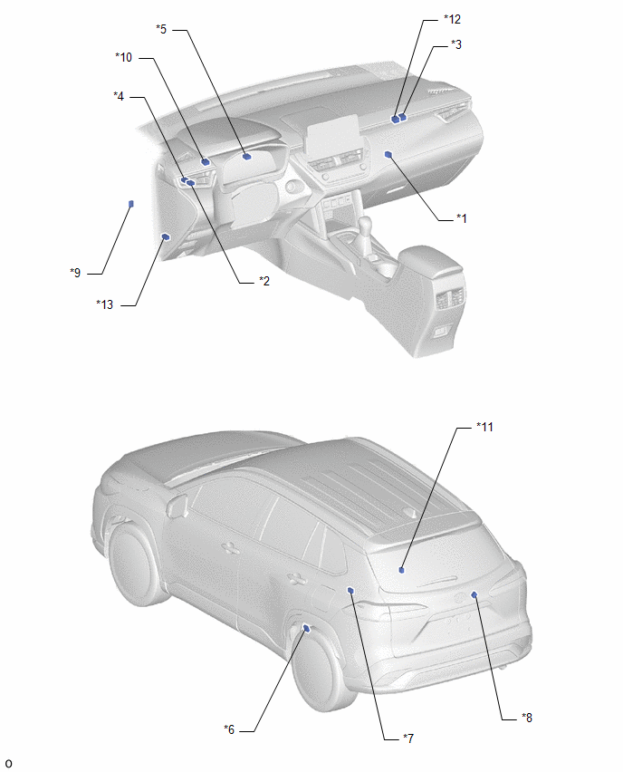
ILLUSTRATION
|
*1 |
NO. 9 GLOBAL CAN JUNCTION CONNECTOR |
*2 |
NO. 11 GLOBAL CAN JUNCTION CONNECTOR |
|
*3 |
NO. 13 GLOBAL CAN JUNCTION CONNECTOR |
*4 |
NO. 14 GLOBAL CAN JUNCTION CONNECTOR |
|
*5 |
NO. 15 GLOBAL CAN JUNCTION CONNECTOR |
*6 |
NO. 16 GLOBAL CAN JUNCTION CONNECTOR |
|
*7 |
NO. 17 GLOBAL CAN JUNCTION CONNECTOR |
*8 |
NO. 18 GLOBAL CAN JUNCTION CONNECTOR |
|
*9 |
NO. 20 GLOBAL CAN JUNCTION CONNECTOR |
*10 |
NO. 21 GLOBAL CAN JUNCTION CONNECTOR |
|
*11 |
NO. 22 GLOBAL CAN JUNCTION CONNECTOR |
*12 |
NO. 2 CAN JUNCTION TERMINAL |
|
*13 |
OPTION CONNECTOR (BUS BUFFER ECU) |
- |
- |


