Toyota Corolla Cross: Parts Location
PARTS LOCATION
ILLUSTRATION
|
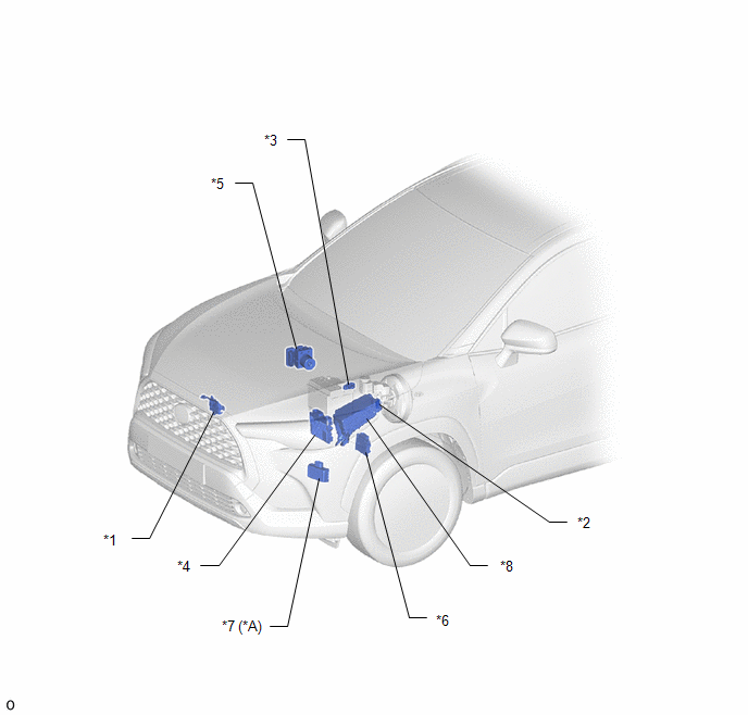
*A | for 9 Speakers |
- | - |
|
*1 | ENGINE HOOD COURTESY SWITCH (HOOD LOCK WITH COURTESY LIGHT SWITCH ASSEMBLY) |
*2 | VACUUM SENSOR ASSEMBLY |
|
*3 | BATTERY STATE SENSOR ASSEMBLY |
*4 | ECM |
|
*5 | SKID CONTROL ECU (BRAKE ACTUATOR ASSEMBLY) |
*6 | TCM |
|
*7 | EXTERNAL BACKUP BOOST CONVERTER (ECO RUN VEHICLE CONVERTER ASSEMBLY) |
*8 | NO. 1 ENGINE ROOM RELAY BLOCK |
ILLUSTRATION
|
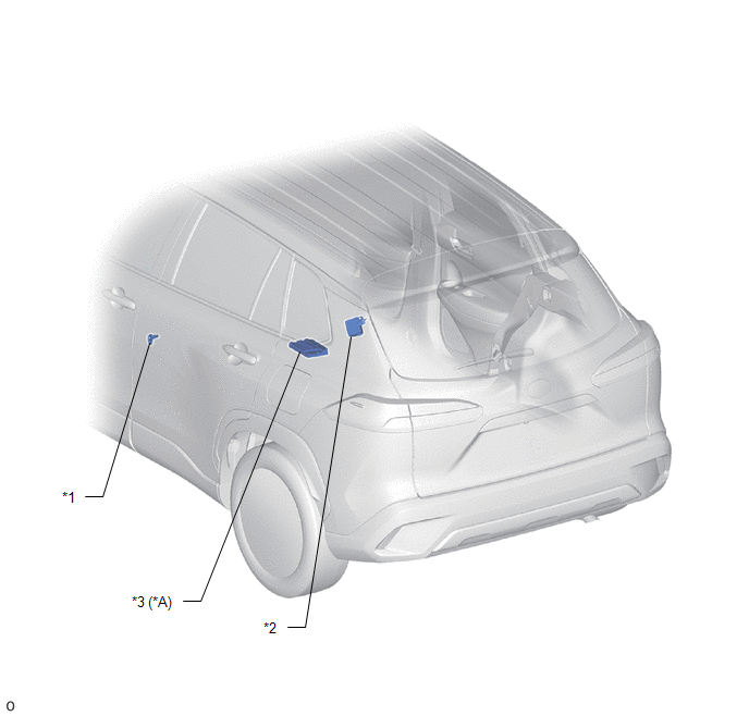
*A | for 9 Speakers |
- | - |
|
*1 | FRONT DOOR COURTESY LIGHT SWITCH ASSEMBLY LH |
*2 | TIRE PRESSURE WARNING ECU AND RECEIVER |
|
*3 | STEREO COMPONENT AMPLIFIER ASSEMBLY |
- | - |
ILLUSTRATION
|
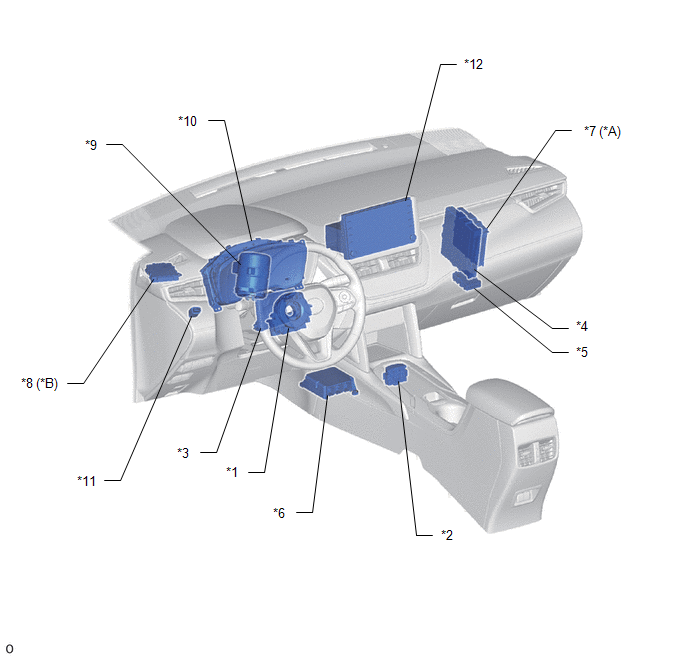
*A | w/ Smart Key System |
*B | w/ Clearance Sonar System |
|
*1 | SPIRAL CABLE SUB-ASSEMBLY |
*2 | STOP AND START SYSTEM CANCEL SWITCH (COMBINATION SWITCH ASSEMBLY) |
|
*3 | AIR CONDITIONING AMPLIFIER ASSEMBLY |
*4 | ENGINE STOP AND START ECU |
|
*5 | CENTRAL GATEWAY ECU (NETWORK GATEWAY ECU) |
*6 | AIRBAG ECU ASSEMBLY |
|
*7 | CERTIFICATION ECU (SMART KEY ECU ASSEMBLY) |
*8 | CLEARANCE WARNING ECU ASSEMBLY |
|
*9 | POWER STEERING ECU ASSEMBLY |
*10 | COMBINATION METER ASSEMBLY |
|
*11 | STOP LIGHT SWITCH ASSEMBLY |
*12 | RADIO AND DISPLAY RECEIVER ASSEMBLY |
ILLUSTRATION
|
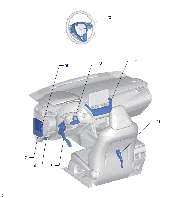
*1 | FRONT SEAT INNER BELT ASSEMBLY LH |
*2 | STEERING PAD SWITCH ASSEMBLY |
|
*3 | STEERING SENSOR |
*4 | AIR CONDITIONING CONTROL ASSEMBLY |
|
*5 | MAIN BODY ECU (MULTIPLEX NETWORK BODY ECU) |
*6 | DLC3 |
|
*7 | POWER DISTRIBUTION BOX ASSEMBLY |
*8 | ACCELERATOR PEDAL WITH SENSOR ROD ASSEMBLY |
ILLUSTRATION
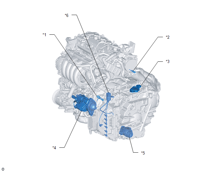
|
*1 | CRANKSHAFT POSITION SENSOR |
*2 | ENGINE COOLANT TEMPERATURE SENSOR |
|
*3 | PARK/NEUTRAL POSITION SWITCH ASSEMBLY |
*4 | STARTER ASSEMBLY |
|
*5 | OIL PUMP WITH MOTOR ASSEMBLY |
*6 | TRANSMISSION WIRE - CVT FLUID TEMPERATURE SENSOR |


