Toyota Corolla Cross: Parts Location
PARTS LOCATION
ILLUSTRATION
|
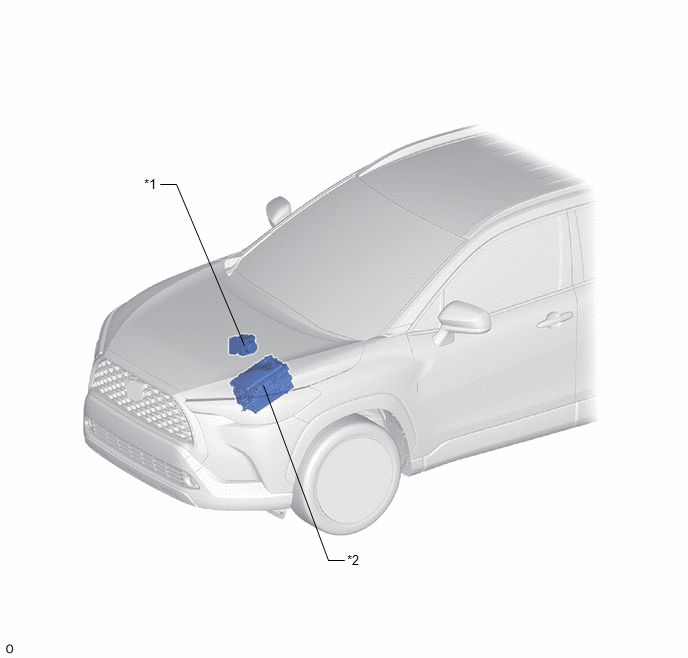
*1 | SKID CONTROL ECU (BRAKE ACTUATOR ASSEMBLY) |
*2 | NO. 1 ENGINE ROOM RELAY BLOCK - IGP-MAIN RELAY |
ILLUSTRATION
|
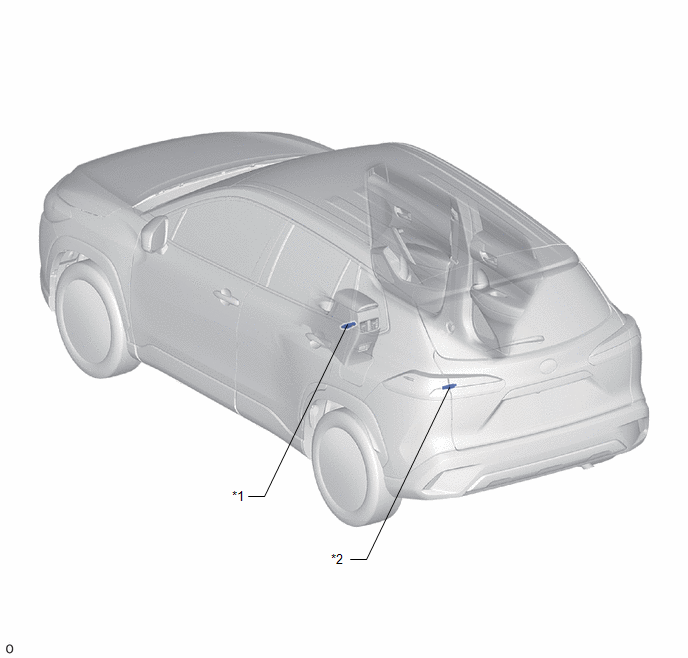
*1 | NO. 1 INDOOR ELECTRICAL KEY ANTENNA ASSEMBLY (FRONT FLOOR) |
*2 | NO. 3 INDOOR ELECTRICAL KEY ANTENNA ASSEMBLY (INSIDE LUGGAGE COMPARTMENT) |
ILLUSTRATION
|
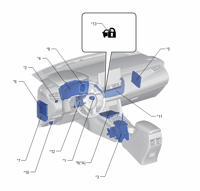
*A | w/ Wireless Charging System |
- | - |
|
*1 | POWER SWITCH |
*2 | STOP LIGHT SWITCH ASSEMBLY |
|
*3 | SHIFT LOCK CONTROL UNIT ASSEMBLY |
*4 | COMBINATION METER ASSEMBLY |
|
*5 | CERTIFICATION ECU (SMART KEY ECU ASSEMBLY) |
*6 | MAIN BODY ECU (MULTIPLEX NETWORK BODY ECU) |
|
*7 | POWER DISTRIBUTION BOX ASSEMBLY - ACC RELAY - IGR NO. 1 RELAY - IGR NO. 2 RELAY - AM2 FUSE - STOP FUSE - ECU-ACC FUSE - ECU-IGR NO. 1 FUSE - ECU-IGR NO. 2 FUSE |
*8 | ID CODE BOX (IMMOBILISER CODE ECU) |
|
*9 | MOBILE WIRELESS CHARGER CRADLE ASSEMBLY |
*10 | DLC3 |
|
*11 | AIR CONDITIONING CONTROL ASSEMBLY |
*12 | AIR CONDITIONER AMPLIFIER ASSY |
|
*13 | SECURITY INDICATOR LIGHT |
- | - |


