Toyota Corolla Cross: Parts Location
PARTS LOCATION
ILLUSTRATION
|
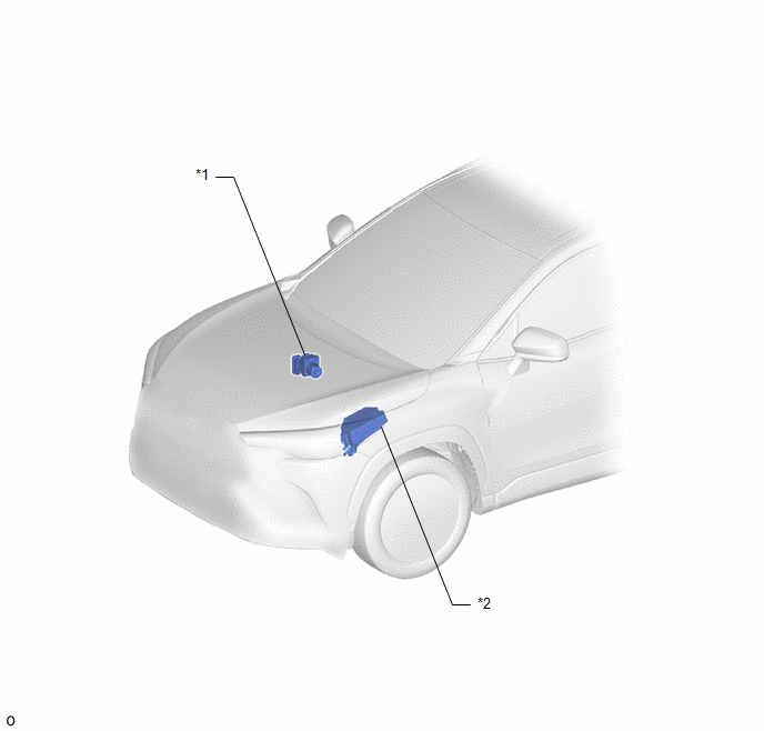
*1 |
BRAKE ACTUATOR ASSEMBLY - SKID CONTROL ECU |
*2 |
NO. 1 ENGINE ROOM RELAY BLOCK - ABS NO. 2 FUSE |
ILLUSTRATION
|
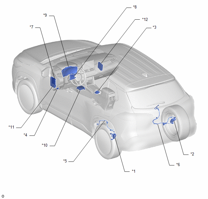
*1 |
PARKING BRAKE ACTUATOR ASSEMBLY LH |
*2 |
PARKING BRAKE ACTUATOR ASSEMBLY RH |
|
*3 |
ELECTRIC PARKING BRAKE SWITCH (ELECTRIC PARKING BRAKE SWITCH ASSEMBLY) |
*4 |
DLC3 |
|
*5 |
NO. 2 PARKING BRAKE WIRE ASSEMBLY |
*6 |
NO. 1 PARKING BRAKE WIRE ASSEMBLY |
|
*7 |
MAIN BODY ECU (MULTIPLEX NETWORK BODY ECU) |
*8 |
AIR CONDITIONING AMPLIFIER ASSEMBLY |
|
*9 |
COMBINATION METER ASSEMBLY |
*10 |
DECELERATION SENSOR (AIRBAG ECU ASSEMBLY) |
|
*11 |
POWER DISTRIBUTION BOX ASSEMBLY - ECU-IGR NO. 4 FUSE |
*12 |
HYBRID VEHICLE CONTROL ECU |


