Toyota Corolla Cross: On-vehicle Inspection
ON-VEHICLE INSPECTION
PROCEDURE
1. INSPECT RADIO SETTING CONDENSER
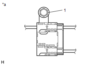
(a) With the radio setting condenser installed, check that there is
no looseness or other abnormalities.
|
(b) Measure the resistance of the radio setting condenser
according to the value(s) in the table below.
Standard Resistance:
|
Tester Connection
|
Condition
|
Specified Condition
|
|
1 - Body ground
|
- Ignition switch off
- Window Defogger turned off
- High mounted stop light off
|
Below 1 Ω
|
|
 |
|
*a
|
Radio Setting Condenser
|
|
|
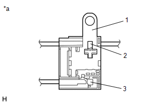
(c) Remove the bolt.
(d) Disengage the clamp and disconnect the radio setting condenser
with wire harness from the vehicle body.
|
(e) Measure the resistance and voltage of the radio setting
condenser according to the value(s) in the table below.
Standard Resistance:
|
Tester Connection
|
Condition
|
Specified Condition
|
|
1 - 2
|
- Ignition switch off
- Window Defogger turned off
- High mounted stop light off
|
10 kΩ or higher
|
|
1 - 3
|
10 kΩ or higher
|
Standard Voltage:
|
Tester Connection
|
Condition
|
Specified Condition
|
|
2 - Body ground
|
- Ignition switch ON
- Window Defogger turned off
|
Below 1 V
|
|
3 - Body ground
|
- Ignition switch ON
- High mounted stop light off
|
Below 1 V
|
|
2 - Body ground
|
- Ignition switch ON
- Window Defogger turned on
|
11 to 14 V
|
|
3 - Body ground
|
- Ignition switch ON
- High mounted stop light on
|
11 to 14 V
|
|
 |
|
*a
|
Radio Setting Condenser
|
|
|
READ NEXT:
REMOVAL
CAUTION / NOTICE / HINT
COMPONENTS (REMOVAL)
Procedure
Part Name Code
1
DECK TRIM SIDE PANEL ASSEMBLY LH
INSTALLATION
CAUTION / NOTICE / HINT
COMPONENTS (INSTALLATION)
Procedure
Part Name Code
1
RADIO SETTING CONDENSER
SEE MORE:
DESCRIPTION The No. 1 cooler thermistor is installed to the evaporator in the air conditioner unit to detect the temperature of the cooled air that has passed through the evaporator, which is used to control the air conditioning system. It sends signals to the air conditioning amplifier assembly. Th
DESCRIPTION This DTC is stored when the SSW1 contact signal, SSW2 contact signal and SSW3 contact signal, which are detected when the ignition switch is operated, do not match.
DTC No. Detection Item
DTC Detection Condition Trouble Area
Note B227862
Engine/Power Switch


