Toyota Corolla Cross: Installation
INSTALLATION
CAUTION / NOTICE / HINT
COMPONENTS (INSTALLATION)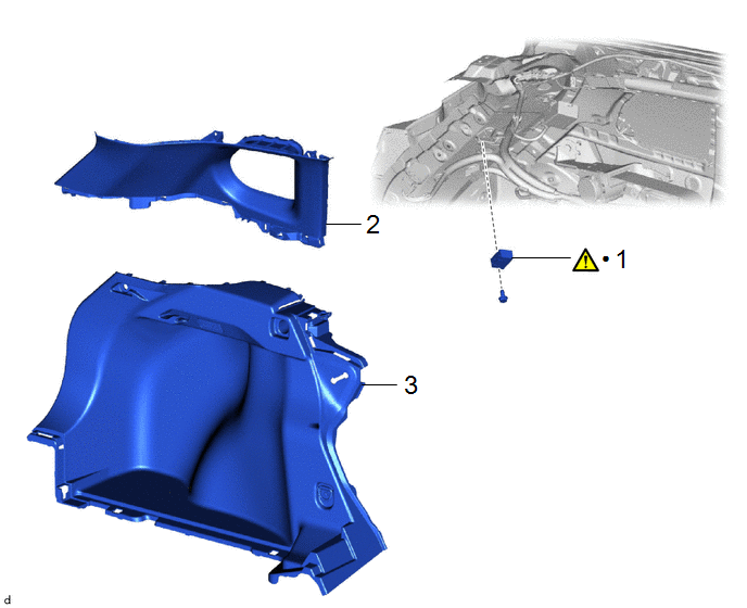
|
Procedure |
Part Name Code |
.png) |
.png) |
.png) |
|
|---|---|---|---|---|---|
|
1 |
RADIO SETTING CONDENSER |
86011A |
|
- |
- |
|
2 |
ROOF SIDE INNER GARNISH ASSEMBLY LH |
62480A |
- |
- |
- |
|
3 |
DECK TRIM SIDE PANEL ASSEMBLY LH |
64740C |
- |
- |
- |
|
● |
Non-reusable part |
- |
- |
PROCEDURE
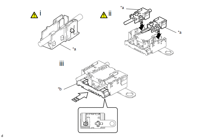
1. INSTALL RADIO SETTING CONDENSER
|
*a |
Terminal Cover |
*b |
Cover |
.png) |
Install in this Direction |
.png) |
Insert in this Direction |
(1) Engage the claw to install a new terminal cover to the wire harness.
NOTICE:
- Make sure to hold the crimped side of the terminal when installing the wire harness to the terminal cover.
- Make sure not to bend the exposed wire when installing the wire harness to the terminal cover.
- Do not use excessive force when inserting the wire harness into the terminal cover.
- If the terminal cover has been deformed during installation, replace the terminal and terminal cover with new ones.
HINT:
Use the same procedure for the other terminal cover.
(2) Engage the claws to install the 2 terminal covers with wire harness to a new radio setting condenser as shown in the illustration.
NOTICE:
- Do not use excessive force when inserting the terminal covers into the condenser.
- If a terminal cover has been deformed during installation, replace the terminal, terminal covers and condenser with new ones.
(3) Insert the cover as shown in the illustration and engage the claw.

(1) Engage the clamp to install the radio setting condenser with wire harness.
(2) Install the bolt.
2. INSTALL ROOF SIDE INNER GARNISH ASSEMBLY LH
3. INSTALL DECK TRIM SIDE PANEL ASSEMBLY LH
Click here .gif)


