Toyota Corolla Cross: No Communication in Immobiliser System (B2796,B2798)
DESCRIPTION
This DTC is stored when a door control transmitter assembly is inserted into the ignition key cylinder but no communication occurs between the door control transmitter assembly and transponder key ECU assembly.
|
DTC No. | Detection Item |
DTC Detection Condition | Trouble Area |
Note |
|---|---|---|---|---|
| B2796 |
No Communication in Immobiliser System |
The key ID code cannot be transmitted to the transponder key ECU assembly (1 trip detection logic*). |
| DTC Output Confirmation Operation:
|
| B2798 |
Communication Malfunction No. 2 |
Key ID code identification cannot be completed within the specified time (1 trip detection logic*). |
| DTC Output Confirmation Operation:
|
- *: Only output while a malfunction is present.
|
Vehicle Condition when Malfunction Detected |
Fail-safe Operation when Malfunction Detected |
|---|---|
|
Engine cannot be started |
- |
|
DTC No. | Data List and Active Test |
|---|---|
|
B2796 | - |
|
B2798 | - |
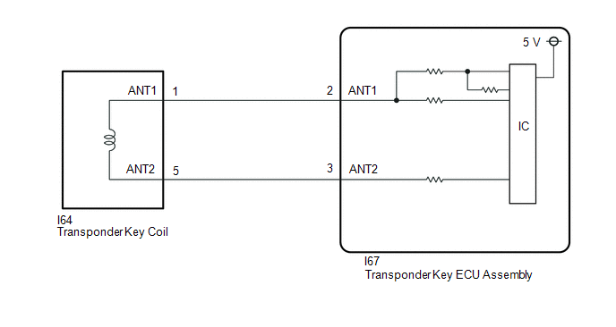
WIRING DIAGRAM
CAUTION / NOTICE / HINT
NOTICE:
- If the door control transmitter assembly is replaced, refer to Registration.
Click here
.gif)
- After repair, confirm that no DTCs are output by performing "DTC Output Confirmation Operation".
PROCEDURE
|
1. | CHECK HARNESS AND CONNECTOR (TRANSPONDER KEY ECU ASSEMBLY - TRANSPONDER KEY COIL) |
(a) Disconnect the I67 transponder key ECU assembly connector.
(b) Disconnect the I64 transponder key coil connector.
(c) Measure the resistance according to the value(s) in the table below.
Standard Resistance:
|
Tester Connection | Condition |
Specified Condition |
|---|---|---|
|
I67-2 (ANT1) - I64-1 (ANT1) |
Always | Below 1 Ω |
|
I67-3 (ANT2) - I64-5 (ANT2) |
Always | Below 1 Ω |
|
I67-2 (ANT1) or I64-1 (ANT1) - Other terminals and body ground |
Always | 10 kΩ or higher |
|
I67-3 (ANT2) or I64-5 (ANT2) - Other terminals and body ground |
Always | 10 kΩ or higher |
| OK | .gif) | REPLACE DOOR CONTROL TRANSMITTER ASSEMBLY |
| NG | | REPAIR OR REPLACE HARNESS OR CONNECTOR |


