Toyota Corolla Cross: Engine Immobiliser System Circuit Short to Battery (B279A12)
DESCRIPTION
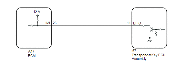
If the communication line (EFIO-IMI) to the transponder key ECU assembly is stuck high (e.g. shorted to +B), the ECM stores this DTC.
|
DTC No. | Detection Item |
DTC Detection Condition | Trouble Area |
Note |
|---|---|---|---|---|
| B279A12 |
Engine Immobiliser System Circuit Short to Battery |
Communication line (EFIO-IMI) between the ECM and transponder key ECU assembly is stuck high. |
| DTC Output Confirmation Operation:
|
|
Vehicle Condition when Malfunction Detected |
Fail-safe Operation when Malfunction Detected |
|---|---|
|
Engine cannot be started (initial ignition occurs and engine cranks, then ignition stops) |
Engine cannot be started |
|
DTC No. | Data List and Active Test |
|---|---|
|
B279A12 | - |
WIRING DIAGRAM
CAUTION / NOTICE / HINT
NOTICE:
- If the transponder key ECU assembly or ECM is replaced, refer to Registration.
Click here
.gif)
- After repair, confirm that no DTCs are output by performing "DTC Output Confirmation Operation".
PROCEDURE
|
1. | CHECK CONNECTION OF CONNECTOR |
(a) Check that the connectors are properly connected to the ECM and transponder key ECU assembly.
OK:
Connectors are properly connected.
| NG | .gif) | CONNECT CONNECTORS PROPERLY |
|
.gif)
| 2. |
CHECK ECM |
(a) Disconnect the I67 transponder key ECU assembly connector.
(b) Measure the voltage according to the value(s) in the table below.
Standard Voltage:
|
Tester Connection | Condition |
Specified Condition |
|---|---|---|
|
I67-11 (EFIO) - Body ground |
Always | 11 to 14 V |
| NG | | GO TO STEP 4 |
|
| 3. |
CHECK TRANSPONDER KEY ECU ASSEMBLY (TERMINAL EFIO) |
(a) Connect the transponder key ECU assembly connector.
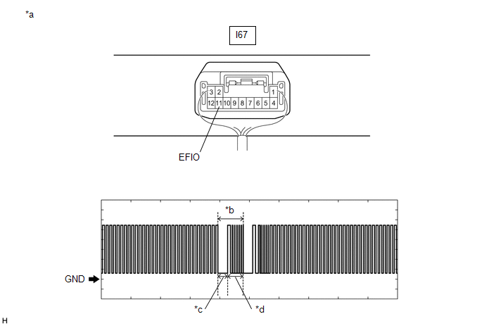
(b) Using an oscilloscope, check the waveform.
|
*a | Component with harness connected (Transponder Key ECU Assembly) |
*b | Waveform |
|
*c | Approximately 160 ms. |
*d | Approximately 270 ms. |
OK:
|
Tester Connection | Condition |
Tool Setting | Specified Condition |
|---|---|---|---|
|
I67-11 (EFIO) - Body ground |
Within 3 seconds of starter operation and initial combustion, or within 3 seconds of ignition switch first being turned to ON after cable disconnected and reconnected to negative (-) auxiliary battery terminal |
2 V/DIV., 500 ms./DIV. |
Pulse generation (See waveform) |
| OK | | REPLACE ECM
|
| NG | | REPLACE TRANSPONDER KEY ECU ASSEMBLY
|
| 4. |
CHECK HARNESS AND CONNECTOR (TRANSPONDER KEY ECU ASSEMBLY - ECM) |
(a) Disconnect the A47 ECM connector.
(b) Measure the resistance according to the value(s) in the table below.
Standard Resistance:
|
Tester Connection | Condition |
Specified Condition |
|---|---|---|
| I67-11 (EFIO) - A47-26 (IMI) |
Always | Below 1 Ω |
|
I67-11 (EFIO) or A47-26 (IMI) - Other terminals and body ground |
Always | 10 kΩ or higher |
| OK | | REPLACE ECM
|
| NG | | REPAIR OR REPLACE HARNESS OR CONNECTOR |


