
Toyota Corolla Cross: Lost Communication with Side Obstacle Detection Control Module "A" Missing Message (U023287)
DESCRIPTION
This DTC is stored when the blind spot monitor sensor LH (B) judges that there is a communication problem with the blind spot monitor sensor RH (A).
|
DTC No. |
Detection Item |
DTC Detection Condition |
Trouble Area |
|---|---|---|---|
|
U023287 |
Lost Communication with Side Obstacle Detection Control Module "A" Missing Message |
The blind spot monitor sensor LH (B) cannot receive signals from the blind spot monitor sensor RH (A) |
|
WIRING DIAGRAM
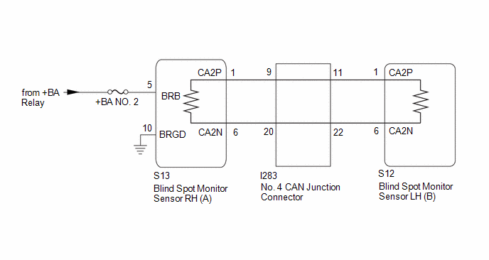
CAUTION / NOTICE / HINT
NOTICE:
- When checking for DTCs, make sure that the blind spot monitor system is turned on.
- Inspect the fuses for circuits related to this system before performing the following procedure.
- Before measuring the resistance of the CAN bus, turn the ignition switch off and leave the vehicle for 1 minute or more without operating the key or any switches, or opening or closing the doors. After that, disconnect the cable from the negative (-) auxiliary battery terminal and leave the vehicle for 1 minute or more before measuring the resistance.
- After turning the ignition switch off, waiting time may be required
before disconnecting the cable from the negative (-) auxiliary battery terminal.
Therefore, make sure to read the disconnecting the cable from the negative
(-) auxiliary battery terminal notices before proceeding with work.
Click here
.gif)
HINT:
- Operating the ignition switch, any other switches or a door triggers related ECU and sensor communication on the CAN. This communication will cause the resistance value to change.
- Even after DTCs are cleared, if a DTC is stored again after driving the vehicle for a while, the malfunction may be occurring due to vibration of the vehicle. In such a case, wiggling the ECUs or wire harness while performing the inspection below may help determine the cause of the malfunction.
PROCEDURE
|
1. |
CHECK DTC OUTPUT (PARKING SUPPORT BRAKE SYSTEM) |
(a) Using the GTS, check for DTCs according to the prompts on the screen.
Body Electrical > Clearance Warning > Trouble Codes|
Result |
Proceed to |
|---|---|
|
U117787 and U117887 are not output |
A |
|
U117787 and U117887 are output |
B |
| B | .gif)
|
GO TO PARKING SUPPORT BRAKE SYSTEM (DTC U117787) |
|
.gif)
|
2. |
CHECK CAN BUS MAIN WIRE |
(a) Turn the ignition switch off.
(b) Disconnect the cable from the negative (-) auxiliary battery terminal.
|
(c) Measure the resistance according to the value(s) in the table below. Standard Resistance:
Result:
|
|
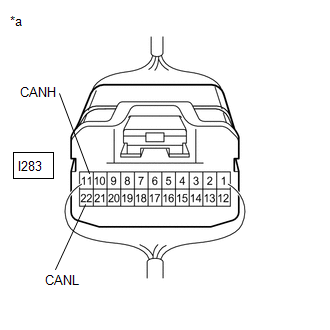
(d) Reconnect the cable to the negative (-) auxiliary battery terminal.
| B |
|
GO TO STEP 7 |
| C |
|
GO TO STEP 11 |
| D |
|
GO TO STEP 11 |
| E |
|
GO TO STEP 11 |
| F |
|
GO TO STEP 11 |
| G |
|
GO TO STEP 15 |
|
|
3. |
CHECK FOR OPEN IN CAN BUS MAIN WIRE (NO. 4 CAN JUNCTION CONNECTOR) |
(a) Disconnect the I283 No. 4 CAN junction connector.
(b) Measure the resistance according to the value(s) in the table below.
Standard Resistance:
|
Tester Connection |
Condition |
Specified Condition |
|---|---|---|
|
I283-11 (CANH) - I283-22 (CANL) |
Cable disconnected from negative (-) auxiliary battery terminal |
108 to 132 Ω |
| NG |
|
GO TO STEP 6 |
|
|
4. |
CHECK FOR OPEN IN CAN BUS MAIN WIRE (NO. 4 CAN JUNCTION CONNECTOR) |
(a) Disconnect the I283 No. 4 CAN junction connector.
(b) Measure the resistance according to the value(s) in the table below.
Standard Resistance:
|
Tester Connection |
Condition |
Specified Condition |
|---|---|---|
|
I283-9 (CANH) - I283-20 (CANL) |
Cable disconnected from negative (-) auxiliary battery terminal |
108 to 132 Ω |
| OK |
|
REPLACE NO. 4 CAN JUNCTION CONNECTOR |
|
|
5. |
CHECK FOR OPEN IN CAN BUS MAIN WIRE (BLIND SPOT MONITOR SENSOR RH (A)) |
(a) Reconnect the I283 No. 1 CAN junction connector.
(b) Disconnect the S13 blind spot monitor sensor RH (A) connector.
(c) Measure the resistance according to the value(s) in the table below.
Standard Resistance:
|
Tester Connection |
Condition |
Specified Condition |
|---|---|---|
|
S13-1 (CA2P) - S13-6 (CA2N) |
Cable disconnected from negative (-) auxiliary battery terminal |
108 to 132 Ω |
| OK |
|
REPLACE BLIND SPOT MONITOR SENSOR RH (A) |
| NG |
|
REPAIR OR REPLACE CAN MAIN WIRE OR CONNECTOR |
|
6. |
CHECK FOR OPEN IN CAN BUS MAIN WIRE (BLIND SPOT MONITOR SENSOR LH (B)) |
(a) Reconnect the I283 No. 4 CAN junction connector.
(b) Disconnect the S12 blind spot monitor sensor LH (B) connector.
(c) Measure the resistance according to the value(s) in the table below.
Standard Resistance:
|
Tester Connection |
Condition |
Specified Condition |
|---|---|---|
|
S12-1 (CA2P) - S12-6 (CA2N) |
Cable disconnected from negative (-) auxiliary battery terminal |
108 to 132 Ω |
| OK |
|
REPLACE BLIND SPOT MONITOR SENSOR LH (B) |
| NG |
|
REPAIR OR REPLACE CAN MAIN WIRE OR CONNECTOR |
|
7. |
CHECK FOR SHORT IN CAN BUS WIRES (NO. 4 CAN JUNCTION CONNECTOR) |
(a) Disconnect the I283 No. 4 CAN junction connector.
(b) Measure the resistance according to the value(s) in the table below.
Standard Resistance:
|
Tester Connection |
Condition |
Specified Condition |
|---|---|---|
|
I283-11 (CANH) - I283-22 (CANL) |
Cable disconnected from negative (-) auxiliary battery terminal |
108 to 132 Ω |
| NG |
|
GO TO STEP 10 |
|
|
8. |
CHECK FOR SHORT IN CAN BUS WIRES (NO. 4 CAN JUNCTION CONNECTOR) |
(a) Disconnect the I283 No. 4 CAN junction connector.
(b) Measure the resistance according to the value(s) in the table below.
Standard Resistance:
|
Tester Connection |
Condition |
Specified Condition |
|---|---|---|
|
I283-9 (CANH) - I283-20 (CANL) |
Cable disconnected from negative (-) auxiliary battery terminal |
108 to 132 Ω |
| OK |
|
REPLACE NO. 4 CAN JUNCTION CONNECTOR |
|
|
9. |
CHECK FOR SHORT IN CAN BUS WIRES (BLIND SPOT MONITOR SENSOR RH (A)) |
(a) Reconnect the I283 No. 4 CAN junction connector.
(b) Disconnect the S13 blind spot monitor sensor RH (A) connector.
(c) Measure the resistance according to the value(s) in the table below.
Standard Resistance:
|
Tester Connection |
Condition |
Specified Condition |
|---|---|---|
|
S13-1 (CA2P) - S13-6 (CA2N) |
Cable disconnected from negative (-) auxiliary battery terminal |
108 to 132 Ω |
| OK |
|
REPLACE BLIND SPOT MONITOR SENSOR RH (A) |
| NG |
|
REPAIR OR REPLACE CAN MAIN WIRE OR CONNECTOR |
|
10. |
CHECK FOR SHORT IN CAN BUS WIRES (BLIND SPOT MONITOR SENSOR LH (B)) |
(a) Reconnect the I283 No. 4 CAN junction connector.
(b) Disconnect the S12 blind spot monitor sensor LH (B) connector.
(c) Measure the resistance according to the value(s) in the table below.
Standard Resistance:
|
Tester Connection |
Condition |
Specified Condition |
|---|---|---|
|
S12-1 (CA2P) - S12-6 (CA2N) |
Cable disconnected from negative (-) auxiliary battery terminal |
108 to 132 Ω |
| OK |
|
REPLACE BLIND SPOT MONITOR SENSOR LH (B) |
| NG |
|
REPAIR OR REPLACE CAN MAIN WIRE OR CONNECTOR |
|
11. |
CHECK FOR SHORT IN CAN BUS WIRES (NO. 4 CAN JUNCTION CONNECTOR) |
(a) Disconnect the I283 No. 4 CAN junction connector.
(b) Measure the resistance according to the value(s) in the table below.
Standard Resistance:
|
Tester Connection |
Condition |
Specified Condition |
|---|---|---|
|
I283-11 (CANH) - Body ground |
Cable disconnected from negative (-) auxiliary battery terminal |
200 Ω or higher |
|
I283-22 (CANL) - Body ground |
Cable disconnected from negative (-) auxiliary battery terminal |
200 Ω or higher |
|
I283-11 (CANH) - +B |
Cable disconnected from negative (-) auxiliary battery terminal |
6 kΩ or higher |
|
I283-22 (CANL) - +B |
Cable disconnected from negative (-) auxiliary battery terminal |
6 kΩ or higher |
| NG |
|
GO TO STEP 14 |
|
|
12. |
CHECK FOR SHORT IN CAN BUS WIRES (NO. 4 CAN JUNCTION CONNECTOR) |
(a) Disconnect the I283 No. 4 CAN junction connector.
(b) Measure the resistance according to the value(s) in the table below.
Standard Resistance:
|
Tester Connection |
Condition |
Specified Condition |
|---|---|---|
|
I283-9 (CANH) -Body ground |
Cable disconnected from negative (-) auxiliary battery terminal |
200 Ω or higher |
|
I283-20 (CANL) - Body ground |
Cable disconnected from negative (-) auxiliary battery terminal |
200 Ω or higher |
|
I283-9 (CANH) - +B |
Cable disconnected from negative (-) auxiliary battery terminal |
6 kΩ or higher |
|
I283-20 (CANL) - +B |
Cable disconnected from negative (-) auxiliary battery terminal |
6 kΩ or higher |
| OK |
|
REPLACE NO. 4 CAN JUNCTION CONNECTOR |
|
|
13. |
CHECK FOR SHORT IN CAN BUS WIRES (BLIND SPOT MONITOR SENSOR RH (A)) |
(a) Reconnect the I283 No. 4 CAN junction connector.
(b) Disconnect the S13 blind spot monitor sensor RH (A) connector.
(c) Measure the resistance according to the value(s) in the table below.
Standard Resistance:
|
Tester Connection |
Condition |
Specified Condition |
|---|---|---|
|
S13-1 (CA2P) - Body ground |
Cable disconnected from negative (-) auxiliary battery terminal |
200 Ω or higher |
|
S13-6 (CA2N) - Body ground |
Cable disconnected from negative (-) auxiliary battery terminal |
200 Ω or higher |
|
S13-1 (CA2P) - +B |
Cable disconnected from negative (-) auxiliary battery terminal |
6 kΩ or higher |
|
S13-6 (CA2N) - +B |
Cable disconnected from negative (-) auxiliary battery terminal |
6 kΩ or higher |
| OK |
|
REPLACE BLIND SPOT MONITOR SENSOR RH (A) |
| NG |
|
REPAIR OR REPLACE CAN MAIN WIRE OR CONNECTOR |
|
14. |
CHECK FOR SHORT IN CAN BUS WIRES (BLIND SPOT MONITOR SENSOR LH (B)) |
(a) Reconnect the I283 No. 4 CAN junction connector.
(b) Disconnect the S12 blind spot monitor sensor LH (B) connector.
(c) Measure the resistance according to the value(s) in the table below.
Standard Resistance:
|
Tester Connection |
Condition |
Specified Condition |
|---|---|---|
|
S12-1 (CA2P) - Body ground |
Cable disconnected from negative (-) auxiliary battery terminal |
200 Ω or higher |
|
S12-6 (CA2N) - Body ground |
Cable disconnected from negative (-) auxiliary battery terminal |
200 Ω or higher |
|
S12-1 (CA2P) - +B |
Cable disconnected from negative (-) auxiliary battery terminal |
6 kΩ or higher |
|
S12-6 (CA2N) - +B |
Cable disconnected from negative (-) auxiliary battery terminal |
6 kΩ or higher |
| OK |
|
REPLACE BLIND SPOT MONITOR SENSOR LH (B) |
| NG |
|
REPAIR OR REPLACE CAN MAIN WIRE OR CONNECTOR |
|
15. |
CHECK HARNESS AND CONNECTOR (BLIND SPOT MONITOR SENSOR RH (A) - BODY GROUND) |
(a) Disconnect the S13 blind spot monitor sensor RH (A) connector.
(b) Measure the resistance according to the value(s) in the table below.
Standard Resistance:
|
Tester Connection |
Condition |
Specified Condition |
|---|---|---|
|
S13-10 (BRGD) - Body ground |
Always |
Below 1 Ω |
| NG |
|
REPAIR OR REPLACE HARNESS OR CONNECTOR |
|
|
16. |
CHECK HARNESS AND CONNECTOR (BLIND SPOT MONITOR SENSOR RH (A) POWER SOURCE) |
(a) Disconnect the S13 blind spot monitor sensor RH (A) connector.
(b) Measure the voltage according to the value(s) in the table below.
Standard Voltage:
|
Tester Connection |
Switch Condition |
Specified Condition |
|---|---|---|
|
S13-5 (BRB) - Body ground |
Ignition switch ON |
11 to 14 V |
|
S13-5 (BRB) - Body ground |
Ignition switch off |
Below 1 V |
| NG |
|
REPAIR OR REPLACE HARNESS OR CONNECTOR |
|
|
17. |
CLEAR DTC |
(a) Reconnect the cable to the negative (-) auxiliary battery terminal.
(b) Turn the ignition switch off.
(c) Turn the ignition switch to ON.
(d) Clear the DTCs.
Body Electrical > Blind Spot Monitor "B" > Clear DTCs
|
|
18. |
CHECK DTC |
(a) Check for DTCs.
Body Electrical > Blind Spot Monitor "B" > Trouble CodesOK:
No DTCs are output.
|
Result |
Proceed to |
|---|---|
|
DTCs are not output |
A |
|
U023287 is output |
B |
|
None of the above conditions are met |
C |
| A |
|
USE SIMULATION METHOD TO CHECK |
| C |
|
GO TO DTC CHART |
|
|
19. |
REPLACE BLIND SPOT MONITOR SENSOR RH (A) |
(a) Replace the blind spot monitor sensor RH (A).
HINT:
Click here
|
|
20. |
CLEAR DTC |
(a) Clear the DTCs.
Body Electrical > Blind Spot Monitor "B" > Clear DTCs
|
|
21. |
RECHECK DTC |
(a) Recheck for DTCs and check if the same DTC is output again.
Body Electrical > Blind Spot Monitor "B" > Trouble CodesOK:
No DTCs are output.
|
Result |
Proceed to |
|---|---|
|
DTCs are not output |
A |
|
U023287 is output |
B |
|
None of the above conditions are met |
C |
| A |
|
END |
| B |
|
REPLACE BLIND SPOT MONITOR SENSOR LH (B) |
| C |
|
GO TO DTC CHART |
READ NEXT:
 Lost Communication with Side Obstacle Detection Control Module "B" Missing Message
(U023387)
Lost Communication with Side Obstacle Detection Control Module "B" Missing Message
(U023387)
DESCRIPTION
This DTC is stored when the blind spot monitor sensor RH (A)
judges that there is a communication problem with the blind spot monitor sensor
LH (B).
DTC No.
Det
Software Incompatibility with Body Control Module Not Programmed (U032251,U032257)
DESCRIPTION
This DTC is stored when the destination information of the main
body ECU (multiplex network body ECU) does not match that of the blind spot monitor
sensors.
DTC No.
Power Source Circuit
DESCRIPTION
This circuit provides power to operate the blind spot monitor
sensor.
WIRING DIAGRAM
CAUTION / NOTICE / HINT
HINT:
Inspect the fuses for circuits related to this system before per
SEE MORE:
 Steering Angle Sensor Module Signal Stuck In Range (C05262A)
DESCRIPTION
The skid control ECU (brake actuator assembly) determines the
steering angle value based on data obtained from the steering sensor, yaw rate and
acceleration sensor (airbag ECU assembly).
DTC No.
Detection Item
DTC Detection Condition
Tro
Cooling is Poor
DESCRIPTION If the cooling effect of the air conditioning system is weak, the following factors may be the cause.
Symptom Factor
Cooling effectiveness is poor
Cooling response is slow
ECO drive mode function (air flow volume is restricted due to ECO drive
