Toyota Corolla Cross: Lost Communication with Front Panel LIN Missing Message (B14B287)
DESCRIPTION
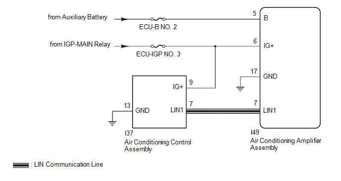
The air conditioning control assembly communicates with the air conditioning amplifier assembly via LIN communication.
If a malfunction occurs in the LIN communication system, the air conditioning amplifier assembly will not operate, even if the air conditioning control assembly is operated.
|
DTC No. | Detection Item |
DTC Detection Condition | Trouble Area |
Memory |
|---|---|---|---|---|
| B14B287 |
Lost Communication with Front Panel LIN Missing Message |
Diagnosis Condition:
Malfunction Status:
Detection Time:
|
| Memorized |
|
Vehicle Condition | |||
|---|---|---|---|
|
Pattern 1 | Pattern 2 | ||
|
Diagnosis Condition | Ignition switch ON |
○ | ○ |
|
Malfunction | Error communication with air conditioning control assembly |
○ | - |
|
Lost communication with air conditioning control assembly |
- | ○ | |
|
Detection Time | Continuously for 10 seconds or more |
Continuously for 10 seconds or more | |
|
Trip Count | 1 trip |
1 trip | |
HINT:
If the conditions of either of these patterns are detected, a DTC will be stored.
WIRING DIAGRAM
CAUTION / NOTICE / HINT
NOTICE:
Inspect the fuses for circuits related to this system before performing the following procedure.
PROCEDURE
| 1. |
CHECK HARNESS AND CONNECTOR (AIR CONDITIONING CONTROL ASSEMBLY - IG POWER SOURCE) |
| (a) Disconnect the I37 air conditioning control assembly connector. |
|
.png)
(b) Measure the voltage according to the value(s) in the table below.
Standard Voltage:
|
Tester Connection | Switch Condition |
Specified Condition |
|---|---|---|
|
I37-9 (IG+) - Body ground |
Ignition switch ON | 11 to 14 V |
| NG | .gif) | REPAIR OR REPLACE HARNESS OR CONNECTOR |
|
.gif)
| 2. |
CHECK HARNESS AND CONNECTOR (AIR CONDITIONING CONTROL ASSEMBLY - BODY GROUND) |
(a) Measure the resistance according to the value(s) in the table below.
Standard Resistance:
|
Tester Connection | Condition |
Specified Condition |
|---|---|---|
|
I37-13 (GND) - Body ground |
Always | Below 1 Ω |
| NG | | REPAIR OR REPLACE HARNESS OR CONNECTOR |
|
| 3. |
CHECK HARNESS AND CONNECTOR (AIR CONDITIONING CONTROL ASSEMBLY - AIR CONDITIONING AMPLIFIER ASSEMBLY) |
(a) Disconnect the I49 air conditioning amplifier assembly connector.
(b) Measure the resistance according to the value(s) in the table below.
Standard Resistance:
|
Tester Connection | Condition |
Specified Condition |
|---|---|---|
|
I37-7 (LIN1) - I49-7 (LIN1) |
Always | Below 1 Ω |
|
I37-7 (LIN1) or I49-7 (LIN1) - Other terminals and body ground |
Always | 10 kΩ or higher |
| NG | | REPAIR OR REPLACE HARNESS OR CONNECTOR |
|
| 4. |
INSPECT AIR CONDITIONING AMPLIFIER ASSEMBLY |
(a) Connect the I49 air conditioning amplifier assembly connector.
| (b) Using an oscilloscope, check the waveform.
OK: Waveform is similar to that shown in the illustration. |
|
.png)
| NG | | REPLACE AIR CONDITIONING AMPLIFIER ASSEMBLY |
|
| 5. |
INSPECT AIR CONDITIONING CONTROL ASSEMBLY |
| (a) Connect the air conditioning control assembly connector. |
|
.png)
(b) Using an oscilloscope, check the waveform.
|
Item | Content |
|---|---|
|
Terminal No. | I37-7 (LIN1) - Body ground |
|
Tool Setting | 2 V/DIV., 20 ms./DIV. |
|
Condition | Ignition switch ON |
OK:
Waveform is similar to that shown in the illustration.
| OK | | REPLACE AIR CONDITIONING AMPLIFIER ASSEMBLY |
| NG | | REPLACE AIR CONDITIONING CONTROL ASSEMBLY |


