Toyota Corolla Cross: Installation
INSTALLATION
CAUTION / NOTICE / HINT
|
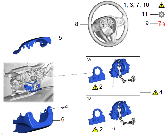
Procedure | Part Name Code |
.png) |
.png) |
 |
|---|---|---|---|---|---|
|
1 | INSPECT SPIRAL CABLE SUB-ASSEMBLY |
- |
|
- | - |
|
2 | STEERING SENSOR |
89245B |
|
- | - |
|
3 | PLACE FRONT WHEELS FACING STRAIGHT AHEAD |
- |
|
- | - |
|
4 | SPIRAL CABLE WITH SENSOR SUB-ASSEMBLY |
- |
|
- | - |
|
5 | UPPER STEERING COLUMN COVER |
45286B | - |
- | - |
|
6 | LOWER STEERING COLUMN COVER |
45287 | - |
- | - |
|
7 | SPIRAL CABLE WITH SENSOR SUB-ASSEMBLY |
- |
|
- | - |
|
8 | STEERING WHEEL ASSEMBLY |
45100 | - |
- | - |
|
9 | CABLE TO NEGATIVE AUXILIARY BATTERY TERMINAL |
- | - |
- | - |
|
10 | INSPECT SRS WARNING LIGHT |
- |
|
- | - |
|
11 | INITIALIZATION AFTER RECONNECTING AUXILIARY BATTERY TERMINAL |
- | - |
- |
|
|
*1 | SPIRAL CABLE SUB-ASSEMBLY |
- | - |
PROCEDURE
1. INSPECT SPIRAL CABLE SUB-ASSEMBLY

|
*a | Check Window |
*b | Matchmark |
|
*c | Top of Flat Cable U-turn |
- | - |
(1) Check if the spiral cable sub-assembly is centered.
OK:
The connector is at the top.
The matchmarks are aligned.
The top of the flat cable U-turn can be checked from the check window.
|
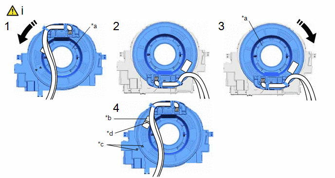
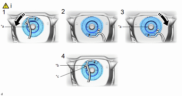
*a | Interlock |
*b | Check Window |
|
*c | Matchmark |
*d | Top of Flat Cable U-turn |
.png) |
Rotation Direction | - |
- |
(1) If the spiral cable sub-assembly is not centered, center it.
NOTICE:
Make sure to observe the following precautions, otherwise the spiral cable sub-assembly may be damaged.
- Release the interlock before rotating the spiral cable sub-assembly.
- Do not rotate the spiral cable sub-assembly using the airbag wire harness.
- Do not rotate the spiral cable sub-assembly with excessive force.
- While pushing on the interlock indicated in the illustration, rotate the spiral cable with sensor sub-assembly counterclockwise slowly by hand until it stops.
NOTICE:
Make sure to rotate the spiral cable with sensor sub-assembly counterclockwise. If rotated clockwise, it may be damaged or centering may no longer be possible.
HINT:
The interlock operates at the top and bottom of the connector.
- If the spiral cable with sensor sub-assembly stops rotating and the connector has moved past the bottom, return the connector to the bottom as shown in the illustration.
- While pushing on the interlock, rotate the spiral cable with sensor sub-assembly clockwise approximately 2.5 times to move the connector from the bottom to the top.
NOTICE:
If the connector is rotated clockwise from the bottom 5 times or more, the spiral cable with sensor sub-assembly may be damaged.
HINT:
The interlock operates at the top and bottom of the connector.
- Check that the spiral cable with sensor sub-assembly is center position.
OK:
The connector is at the top.
The matchmarks are aligned.
The colored roller or the top of the flat cable U-turn can be checked from the check window.
NOTICE:
If the spiral cable with sensor sub-assembly cannot be centered, it is possible that the spiral cable sub-assembly is broken. Replace the spiral cable sub-assembly with a new one.
2. INSTALL STEERING SENSOR
|
|
NOTICE: Remove the steering sensor from the spiral cable sub-assembly only when replacing the spiral cable sub-assembly. |
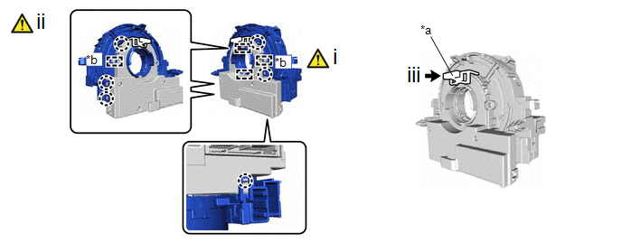
(a) Align the 2 pins and 2 guides, and engage the 6 claws to install the spiral cable sub-assembly to the steering sensor.
|
*a | Lock Pin |
*b | Guide |
(1) Align the guides to install the steering sensor to the spiral cable sub-assembly.
(2) Engage the claws to install the steering sensor to the spiral cable sub-assembly.
NOTICE:
- Do not remove the lock pin before the spiral cable sub-assembly is installed to the steering sensor.
- Do not damage the pins of the spiral cable sub-assembly or guides of the steering sensor.
- The spiral cable sub-assembly can be rotated up to 30° even when the interlock is engaged. Therefore, make sure that both guides are aligned properly when installing the spiral cable sub-assembly to the steering sensor.
(3) Remove the lock pin from the steering sensor.
3. PLACE FRONT WHEELS FACING STRAIGHT AHEAD

4. INSTALL SPIRAL CABLE WITH SENSOR SUB-ASSEMBLY
|
|
NOTICE:
|
.png)
|
*A | w/ Smart Key System |
*B | w/o Smart Key System |
|
*a | Illumination off |
- | - |
(1) Check that the ignition switch is off.
(2) Check that the cable is disconnected from the negative (-) auxiliary battery terminal.
CAUTION:
- Wait at least 90 seconds after disconnecting the cable from the negative (-) auxiliary battery terminal to disable the SRS system.
- If the airbag deploys for any reason, it may cause a serious accident.
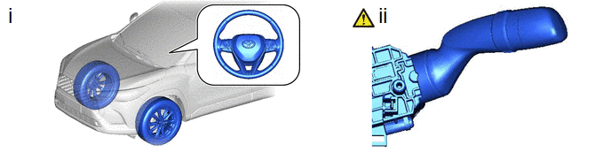
(1) Check that the front wheels are aligned facing straight ahead.
(2) Set the turn signal switch to the neutral position.
NOTICE:
If it is not in the neutral position, the turn signal switch cancel ratchet may snap.
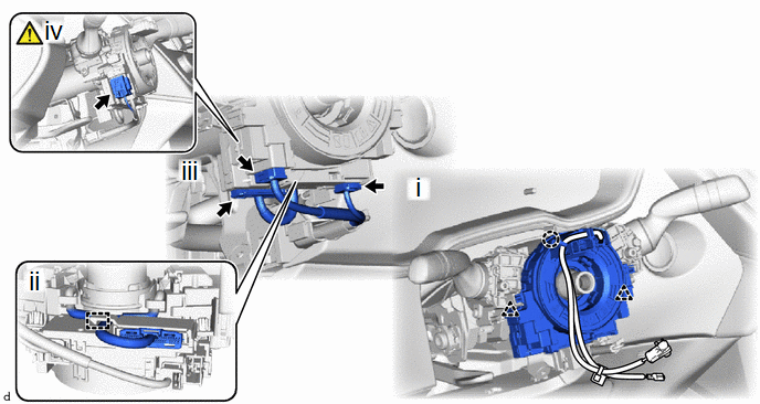
(1) Engage the claw and clip to install the spiral cable with sensor sub-assembly.
(2) Install the wire harness to the spiral cable with sensor sub-assembly.
(3) Connect each connector.
(4) Connect the airbag connector.
NOTICE:
When connecting any airbag connector, take care not to damage the airbag wire harness.
HINT:
Refer to How to Connect or Disconnect Airbag Connector:
Click here
.gif)
5. INSTALL UPPER STEERING COLUMN COVER
6. INSTALL LOWER STEERING COLUMN COVER
7. ADJUST SPIRAL CABLE WITH SENSOR SUB-ASSEMBLY
|
|
NOTICE: Do not rotate the spiral cable with sensor sub-assembly with the battery connected and the ignition switch on (IG). |
|
*A | w/ Smart Key System |
*B | w/o Smart Key System |
|
*a | Illumination off |
- | - |
(1) Check that the ignition switch is off.
(2) Check that the cable is disconnected from the negative (-) auxiliary battery terminal.
CAUTION:
- Wait at least 90 seconds after disconnecting the cable from the negative (-) auxiliary battery terminal to disable the SRS system.
- If the airbag deploys for any reason, it may cause a serious accident.

|
*a | Check Window |
*b | Top of Flat Cable U-turn |
(1) Check that the spiral cable with sensor sub-assembly is center position.
OK:
The connector is at the top.
The top of the flat cable U-turn can be checked from the check window.
|
*a | Interlock |
*b | Check Window |
|
*c | Top of Flat Cable U-turn |
- | - |
|
|
Rotation Direction | - |
- |
(1) If the spiral cable with sensor sub-assembly is not centered, center it.
NOTICE:
Failure to observe the following precautions may result in damage to the spiral cable with sensor sub-assembly.
- When rotating the spiral cable with sensor sub-assembly, make sure to push on the interlock to release the interlock.
- Do not turn the spiral cable with sensor sub-assembly using the airbag wire harness.
- Do not forcibly rotate the part.
- While pushing on the interlock indicated in the illustration, rotate the spiral cable with sensor sub-assembly counterclockwise slowly by hand until it stops.
NOTICE:
If the connector is rotated clockwise from the bottom 5 times or more, the spiral cable with sensor sub-assembly may be damaged.
HINT:
The interlock operates at the top and bottom of the connector.
- If the spiral cable with sensor sub-assembly stops rotating and the connector has moved past the bottom, return the connector to the bottom as shown in the illustration.
- While pushing on the interlock, rotate the spiral cable with sensor sub-assembly clockwise approximately 2.5 times to move the connector from the bottom to the top.
NOTICE:
If the connector is rotated clockwise from the bottom 5 times or more, the spiral cable with sensor sub-assembly may be damaged.
HINT:
The interlock operates at the top and bottom of the connector.
- Check that the spiral cable with sensor sub-assembly is center position.
OK:
The connector is at the top.
The colored roller or the top of the flat cable U-turn can be checked from the check window.
NOTICE:
If the spiral cable sub-assembly cannot be centered, it is possible that the spiral cable sub-assembly is broken. Replace the spiral cable sub-assembly with a new one.
8. INSTALL STEERING WHEEL ASSEMBLY
Click here
9. CONNECT CABLE TO NEGATIVE AUXILIARY BATTERY TERMINAL
- for Gasoline Model
Click here
- for HEV Model
Click here
10. INSPECT SRS WARNING LIGHT
|
|
Click here |
11. INITIALIZATION AFTER RECONNECTING AUXILIARY BATTERY TERMINAL
HINT:
When disconnecting and reconnecting the auxiliary battery, there is an automatic learning function that completes learning when the respective system is used.
Click here


