Toyota Corolla Cross: Installation
INSTALLATION
CAUTION / NOTICE / HINT
COMPONENTS (INSTALLATION)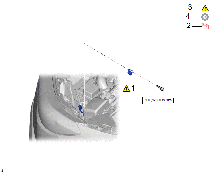
|
Procedure | Part Name Code |
.png) |
.png) |
 |
|---|---|---|---|---|---|
|
1 | FRONT AIRBAG SENSOR |
89174A |
|
- | - |
|
2 | CABLE TO NEGATIVE AUXILIARY BATTERY TERMINAL |
- | - |
- | - |
|
3 | INSPECT SRS WARNING LIGHT |
- |
|
- | - |
|
4 | INITIALIZATION AFTER RECONNECTING AUXILIARY BATTERY TERMINAL |
- | - |
- |
|
.png) |
Tightening torque for "Major areas involving basic vehicle performance such as moving/turning/stopping": N*m (kgf*cm, ft.*lbf) |
- | - |
PROCEDURE
1. INSTALL FRONT AIRBAG SENSOR
.png)
|
*A | w/ Smart Key System |
*B | w/o Smart Key System |
|
*a | Illumination off |
- | - |
(1) Check that the ignition switch is off.
(2) Check that the cable is disconnected from the negative (-) auxiliary battery terminal.
CAUTION:
- Wait at least 90 seconds after disconnecting the cable from the negative (-) auxiliary battery terminal to disable the SRS system.
- If the airbag deploys for any reason, it may cause a serious accident.
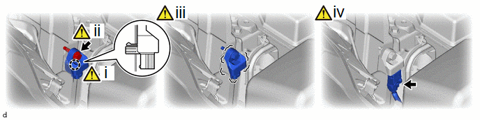
(1) Engage the claw to hold the front airbag sensor in place.
NOTICE:
If the front airbag sensor has been dropped, replace it with a new one.
(2) Install the bolt.
Torque:
9.0 N·m {92 kgf·cm, 80 in·lbf}
(3) Check that there is no looseness in the installation parts of the front airbag sensor.
NOTICE:
- When installing the front airbag sensor, be careful that the SRS wiring does not interfere with or is not pinched between other parts.
- Tighten the nut while holding the front airbag sensor because the front airbag sensor guide is easily damaged.
(4) Connect the airbag connector.
NOTICE:
When connecting any airbag connector, take care not to damage the airbag wire harness.
HINT:
Refer to How to Connect or Disconnect Airbag Connector:
Click here
.gif)
2. CONNECT CABLE TO NEGATIVE AUXILIARY BATTERY TERMINAL
- for Gasoline Model
Click here
- for HEV Model
Click here
3. INSPECT SRS WARNING LIGHT
|
|
Click here |
4. INITIALIZATION AFTER RECONNECTING AUXILIARY BATTERY TERMINAL
HINT:
When disconnecting and reconnecting the auxiliary battery, there is an automatic learning function that completes learning when the respective system is used.
Click here


