Toyota Corolla Cross: Installation
INSTALLATION
CAUTION / NOTICE / HINT
COMPONENTS (INSTALLATION)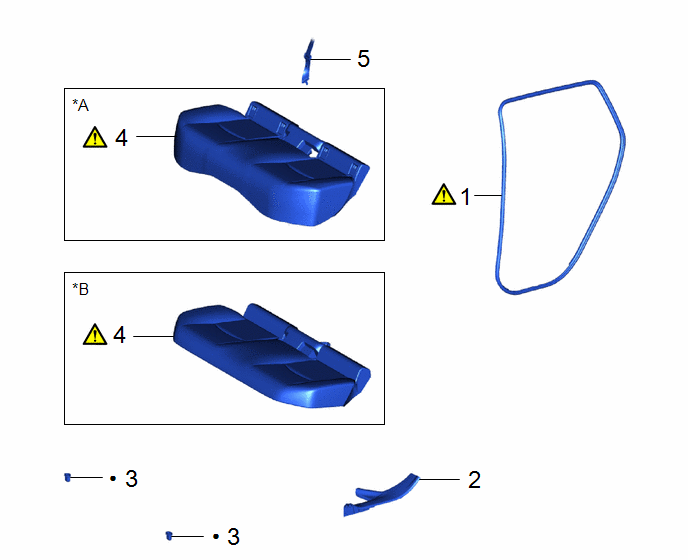
|
Procedure | Part Name Code |
.png) |
.png) |
 |
|---|---|---|---|---|---|
|
1 | REAR DOOR OPENING TRIM WEATHERSTRIP |
62332C |
|
- | - |
|
2 | REAR DOOR SCUFF PLATE |
67918A | - |
- | - |
|
3 | REAR SEAT CUSHION LOCK HOOK |
72693 | - |
- | - |
|
4 | BENCH TYPE REAR SEAT CUSHION ASSEMBLY |
- |
|
- | - |
|
5 | REAR CENTER SEAT OUTER BELT ASSEMBLY |
73350C | - |
- | - |
.gif)
|
*A | for Gasoline Model |
*B | for HEV Model |
|
● | Non-reusable part |
- | - |
CAUTION / NOTICE / HINT
HINT:
- Use the same procedure for the RH side and LH side.
- The following procedure is for the LH side.
PROCEDURE
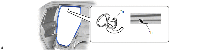
1. INSTALL REAR DOOR OPENING TRIM WEATHERSTRIP
|
*a | Paint Mark |
*b | Cutout |
(1) Align the paint mark on the rear door opening trim weatherstrip with the cutout on the vehicle body, and install the rear door opening trim weatherstrip.
NOTICE:
- Make sure that the paint mark is aligned with the cutout when installing the rear door opening trim weatherstrip, otherwise water ingress may occur.
- After installation, check that the corners fit correctly.
HINT:
- Make sure to install the part of the rear door opening trim weatherstrip near the paint mark first.
- The color of the paint marks on the rear door opening trim weatherstrip LH and rear door opening trim weatherstrip RH are different. Paint mark
Location
Color
for LH Side
Green
for RH Side
White
2. INSTALL REAR DOOR SCUFF PLATE
3. INSTALL REAR SEAT CUSHION LOCK HOOK
4. INSTALL BENCH TYPE REAR SEAT CUSHION ASSEMBLY
|
|
|
5. CONNECT REAR CENTER SEAT OUTER BELT ASSEMBLY


