Toyota Corolla Cross: Installation
INSTALLATION
CAUTION / NOTICE / HINT
COMPONENTS (INSTALLATION)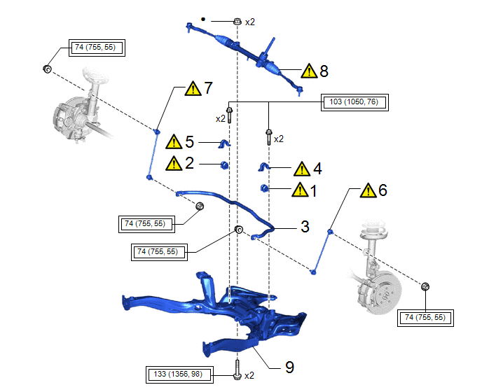
|
Procedure |
Part Name Code |
.png) |
.png) |
.png) |
|
|---|---|---|---|---|---|
|
1 |
FRONT STABILIZER BAR BUSH LH |
48815E |
|
- |
- |
|
2 |
FRONT STABILIZER BAR BUSH RH |
48815D |
|
- |
- |
|
3 |
FRONT STABILIZER BAR |
48811 |
|
- |
- |
|
4 |
FRONT NO. 1 STABILIZER BRACKET LH |
48829A |
|
- |
- |
|
5 |
FRONT NO. 1 STABILIZER BRACKET RH |
48824A |
|
- |
- |
|
6 |
FRONT STABILIZER LINK ASSEMBLY LH |
48810 |
|
- |
- |
|
7 |
FRONT STABILIZER LINK ASSEMBLY RH |
48820B |
|
- |
- |
|
8 |
STEERING LINK ASSEMBLY |
- |
|
- |
- |
|
9 |
FRONT SUSPENSION CROSSMEMBER SUB-ASSEMBLY |
51201F |
- |
- |
- |
.png) |
Tightening torque for "Major areas involving basic vehicle performance such as moving/turning/stopping" : N*m (kgf*cm, ft.*lbf) |
● |
Non-reusable part |
PROCEDURE
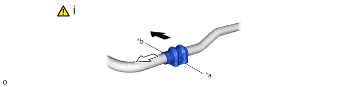
1. INSTALL FRONT STABILIZER BAR BUSH LH
|
|
NOTICE:
|
|
*a |
Cutout |
*b |
Stopper |
.png) |
Front of the Vehicle |
 |
Outside of the Vehicle |
(1) Install the front stabilizer bar bushing LH to the front stabilizer bar as shown in the illustration.
2. INSTALL FRONT STABILIZER BAR BUSH RH
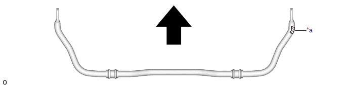
3. INSTALL FRONT STABILIZER BAR
|
|
NOTICE: Make sure that the identification mark is positioned on the right side of the vehicle. |
|
*a |
Identification Mark |
- |
- |
|
|
Front of the Vehicle |
- |
- |
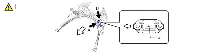
4. INSTALL FRONT NO. 1 STABILIZER BRACKET LH
|
*a |
Arrow Mark |
- |
- |
|
|
Front of the Vehicle |
- |
- |
(1) Install the front No. 1 stabilizer bracket LH to the front suspension crossmember sub-assembly with the 2 bolts.
Torque:
103 N·m {1050 kgf·cm, 76 ft·lbf}
NOTICE:
- Make sure to install the front No. 1 stabilizer bracket LH with its arrow facing the front of the vehicle.
- Temporarily tighten the bolt (B) and then fully tighten the 2 bolts in the order of (A) and (B).
5. INSTALL FRONT NO. 1 STABILIZER BRACKET RH
6. INSTALL FRONT STABILIZER LINK ASSEMBLY LH
|
|
Click here |
7. INSTALL FRONT STABILIZER LINK ASSEMBLY RH
8. INSTALL STEERING LINK ASSEMBLY
|
|
Click here |
9. INSTALL FRONT SUSPENSION CROSSMEMBER SUB-ASSEMBLY
Click here .gif)


