Toyota Corolla Cross: Installation
INSTALLATION
CAUTION / NOTICE / HINT
COMPONENTS (INSTALLATION)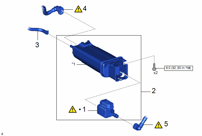
|
Procedure | Part Name Code |
.png) |
.png) |
 |
|---|---|---|---|---|---|
|
1 | LEAK DETECTION PUMP SUB-ASSEMBLY |
77740R |
|
- | - |
|
2 | CANISTER (CHARCOAL CANISTER ASSEMBLY) |
77740 | - |
- | - |
|
3 | CHARCOAL CANISTER HOSE |
77759A | - |
- | - |
|
4 | NO. 2 FUEL TANK VENT HOSE SUB-ASSEMBLY |
77404B |
|
- | - |
|
5 | FUEL TANK VENT HOSE SUB-ASSEMBLY |
77404 |
|
- | - |
|
*1 | CHARCOAL CANISTER SUB-ASSEMBLY |
- | - |
.png) |
N*m (kgf*cm, ft.*lbf): Specified torque |
● | Non-reusable part |
|
Procedure | Part Name Code |
|
|
| |
|---|---|---|---|---|---|
|
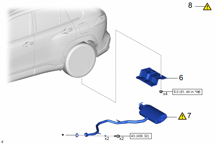
6 | MAIN MUFFLER UPPER HEAT INSULATOR |
58327D | - |
- | - |
|
7 | TAIL EXHAUST PIPE ASSEMBLY |
17430 |
|
- | - |
|
8 | INSPECT FOR EXHAUST GAS LEAK |
- |
|
- | - |
|
|
N*m (kgf*cm, ft.*lbf): Specified torque |
● | Non-reusable part |
PROCEDURE
1. INSTALL LEAK DETECTION PUMP SUB-ASSEMBLY
|
|
HINT: Only perform this procedure when replacement of the leak detection pump sub-assembly is necessary. |
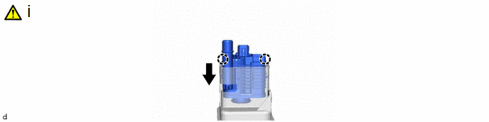
(1) Engage the 2 claws to install a new leak detection pump sub-assembly to the charcoal canister sub-assembly.
NOTICE:
- Do not allow foreign matter such as grease, oil or water to adhere to the O-ring.
- Ensure that the claws are engaged properly.
2. INSTALL CANISTER (CHARCOAL CANISTER ASSEMBLY)
Torque:
9.0 N·m {92 kgf·cm, 80 in·lbf}
3. CONNECT CHARCOAL CANISTER HOSE
4. CONNECT NO. 2 FUEL TANK VENT HOSE SUB-ASSEMBLY
|
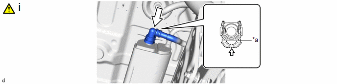
*a | Retainer |
- | - |
.png) |
Push | - |
- |
(1) Push the No. 2 fuel tank vent hose onto the canister (charcoal canister assembly) and push in the retainer to engage the lock claws.
Click here .gif)
NOTICE:
- Check that there are no scratches or foreign matter around the connecting parts of the tube connector and pipe (canister (charcoal canister assembly)) before performing this work.
- After connecting the No. 2 fuel tank vent hose, check that the No. 2 fuel tank vent hose is securely connected by pulling on the tube connector.
5. CONNECT FUEL TANK VENT HOSE SUB-ASSEMBLY
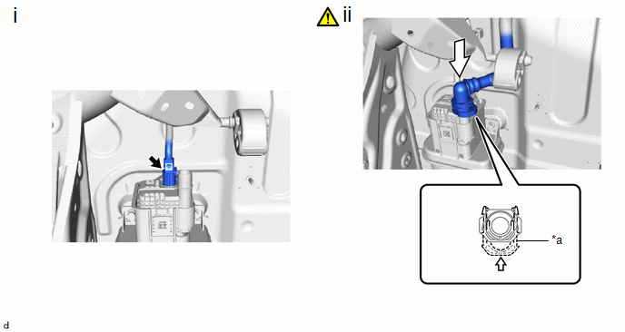
|
*a | Retainer |
- | - |
|
|
Push | - |
- |
(1) Connect the leak detection pump sub-assembly connector.
(2) Push in the fuel tank vent hose sub-assembly onto the leak detection pump sub-assembly and push in the retainer to engage the lock claws.
Click here
NOTICE:
- Check that there are no scratches or foreign matter around the connecting parts of the tube connector and pipe (leak detection pump sub-assembly) before performing this work.
- After connecting the fuel tank vent hose sub-assembly, check that the fuel tank vent hose sub-assembly is securely connected by pulling on the tube connector.
6. INSTALL MAIN MUFFLER UPPER HEAT INSULATOR
Torque:
5.0 N·m {51 kgf·cm, 44 in·lbf}
7. INSTALL TAIL EXHAUST PIPE ASSEMBLY
|
|
Click here |
8. INSPECT FOR EXHAUST GAS LEAK
Click here


