Toyota Corolla Cross: Installation
INSTALLATION
CAUTION / NOTICE / HINT
COMPONENTS (INSTALLATION)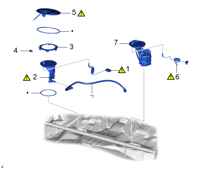
|
Procedure | Part Name Code |
.png) |
.png) |
 |
|---|---|---|---|---|---|
|
1 | NO. 2 FUEL SENDER GAUGE ASSEMBLY |
83320B |
|
- | - |
|
2 | FUEL TANK VENT TUBE ASSEMBLY |
77010 |
|
- | - |
|
3 | FUEL PUMP GAUGE RETAINER |
77144 | - |
- | - |
|
4 | NO. 1 FUEL TUBE CLAMP |
77285D | - |
- | - |
|
5 | REAR FLOOR SERVICE HOLE COVER |
58325M |
|
- | - |
|
6 | FUEL SENDER GAUGE ASSEMBLY |
83320 |
|
- | - |
|
7 | FUEL SUCTION WITH PUMP AND GAUGE TUBE ASSEMBLY |
77020A | - |
- | - |
|
*1 | FUEL RETUN VENT TUBE SUB-ASSEMBLY | ||
|
● | Non-reusable part |
- | - |
PROCEDURE
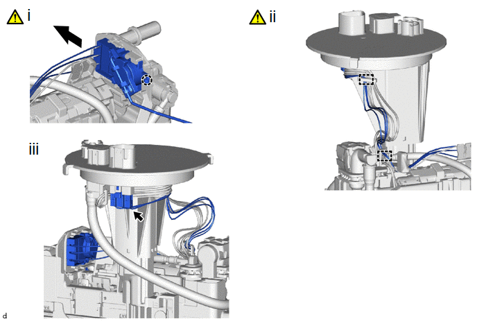
1. INSTALL NO. 2 FUEL SENDER GAUGE ASSEMBLY
(1) Attach the claw and install the No. 2 fuel sender gauge assembly.
NOTICE:
Be careful not to bend the arm of the fuel sender gauge assembly.
(2) Attach the 2 clamps and connect the wire harness to the fuel tank vent tube assembly.
NOTICE:
Do not damage the wire harness.
(3) Connect the connector to the fuel tank vent tube assembly.
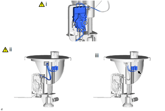
2. INSTALL FUEL TANK VENT TUBE ASSEMBLY
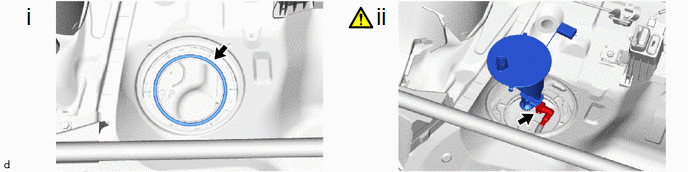
(1) Install a new gasket to the fuel tank assembly.
(2) Connect the fuel return vent tube sub-assembly and set the fuel tank vent tube assembly to the fuel tank assembly.
Click here .gif)
.png)
|
*1 | Fuel Return Vent Tube Sub-assembly |
.png) |
Front of the Vehicle |
- Make sure to correctly assemble the fuel return vent tube sub-assembly as shown in the illustration. If assembled incorrectly, the fuel sender gauge assembly (No. 2 fuel sender gauge assembly) may catch on the fuel return vent tube resulting in incorrect operation of the fuel sender gauge assembly (No. 2 fuel sender gauge assembly) and an incorrect value being displayed on the fuel gauge.
- When connecting the fuel tube connector, do not excessively pull on the fuel return vent tube sub-assembly.
- Be careful not to bend the arm of the No. 2 fuel sender gauge assembly.
3. INSTALL FUEL PUMP GAUGE RETAINER
|
|
HINT: Perform the same procedure as for the fuel suction tube with pump and gauge assembly. Click here |
4. INSTALL NO.1 FUEL TUBE CLAMP
Click here
5. INSTALL REAR FLOOR SERVICE HOLE COVER (for RH Side)
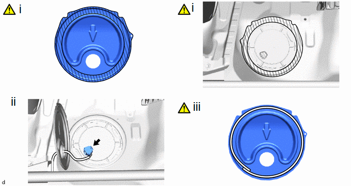
(1) Remove any remaining butyl tape from the rear floor service hole cover and body.
(2) Connect the connector to the fuel tank vent tube assembly.
(3) Install the rear floor service hole cover with new butyl tape.
NOTICE:
Securely install the rear floor service hole cover.
6. INSTALL FUEL SENDER GAUGE ASSEMBLY
(1) Attach the claw and install the fuel sender gauge assembly.
NOTICE:
Be careful not to bend the arm of the fuel sender gauge assembly.
(2) Attach the 2 clamps and connect the wire harness.
NOTICE:
Do not damage the wire harness.
(3) Connect the connector to the fuel suction plate sub-assembly.
7. INSTALL FUEL SUCTION WITH PUMP AND GAUGE TUBE ASSEMBLY
Click here


