Toyota Corolla Cross: Installation
INSTALLATION
CAUTION / NOTICE / HINT
COMPONENTS (INSTALLATION)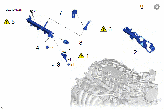
|
Procedure | Part Name Code |
.png) |
.png) |
 |
|---|---|---|---|---|---|
|
1 | PORT FUEL INJECTOR ASSEMBLY |
23250F |
|
- | - |
|
2 | NO. 5 ENGINE WIRE |
82125N | - |
- | - |
|
3 | INJECTOR VIBRATION INSULATOR |
23291 | - |
- | - |
|
4 | FUEL DELIVERY SPACER |
23891 | - |
- | - |
|
5 | FUEL DELIVERY PIPE SUB-ASSEMBLY |
23807 |
|
- | - |
|
6 | FUEL TUBE SUB-ASSEMBLY |
23910A |
|
- | - |
|
7 | FUEL PIPE CLAMP |
23841K | - |
- | - |
|
8 | NO. 2 FUEL PRESSURE SENSOR |
89458H | - |
- | - |
|
9 | PERFORM INITIALIZATION |
- | - |
- |
|
.png) |
Tightening torque for "Major areas involving basic vehicle performance such as moving/turning/stopping" : N*m (kgf*cm, ft.*lbf) |
● | Non-reusable part |
CAUTION / NOTICE / HINT
NOTICE:
This procedure includes the installation of small-head bolts. Refer to Small-Head Bolts of Basic Repair Hint to identify the small-head bolts.
Click here .gif)
PROCEDURE
1. INSTALL PORT FUEL INJECTOR ASSEMBLY
|
|
NOTICE: Perform "Inspection After Repair" after replacing a port fuel injector assembly. Click here |
|
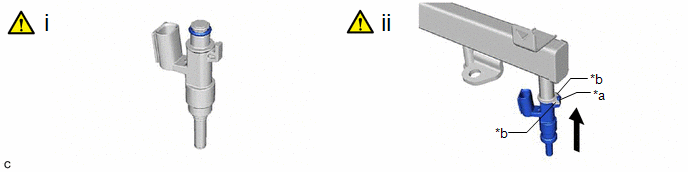
*a | Stopper |
*b | Claw |
(1) Apply a light coat of spindle oil or gasoline to 4 new O-rings, and install one to each port fuel injector assembly.
NOTICE:
Check that there is no damage or foreign matter on the groove of the port fuel injector assembly when installing the O-ring to each port fuel injector assembly.
(2) Install the 4 port fuel injector assemblies to the fuel delivery pipe sub-assembly.
NOTICE:
- Make sure that the port fuel injector assembly is located within the stopper as shown in the illustration.
- Check that the port fuel injector assembly installation holes of the fuel delivery pipe sub-assembly are not damaged and are free of foreign matter.
- Make sure that the O-ring is not damaged, twisted or moved out of place when installing the port fuel injector assembly.
2. INSTALL NO. 5 ENGINE WIRE
3. INSTALL INJECTOR VIBRATION INSULATOR
4. INSTALL FUEL DELIVERY SPACER
5. INSTALL FUEL DELIVERY PIPE SUB-ASSEMBLY
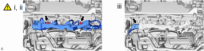
(1) Place the fuel delivery pipe sub-assembly with the 4 port fuel injector assemblies onto the cylinder head sub-assembly.
NOTICE:
Be careful not to drop the port fuel injector assemblies when installing the fuel delivery pipe sub-assembly.
(2) Install the fuel delivery pipe sub-assembly with the port fuel injector assemblies with the 2 bolts.
Torque:
28.5 N·m {291 kgf·cm, 21 ft·lbf}
(3) Connect the No. 5 engine wire connector.
6. CONNECT FUEL TUBE SUB-ASSEMBLY
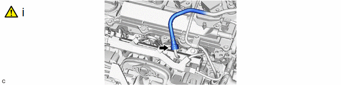
(1) Connect the fuel tube sub-assembly to the fuel delivery pipe sub-assembly.
Click here
7. INSTALL FUEL PIPE CLAMP
8. INSTALL NO. 2 FUEL PRESSURE SENSOR
Click here
9. PERFORM INITIALIZATION
(a) Perform "Inspection After Repair" after replacing a port fuel injector assembly.
Click here


