Toyota Corolla Cross: Installation
INSTALLATION
CAUTION / NOTICE / HINT
COMPONENTS (INSTALLATION)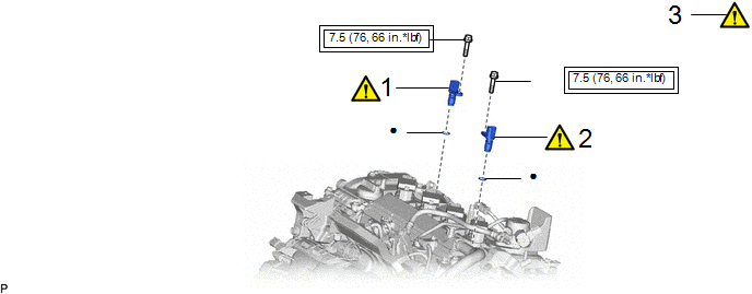
|
Procedure | Part Name Code |
.png) |
.png) |
 |
|---|---|---|---|---|---|
|
1 | CAMSHAFT POSITION SENSOR (for Exhaust Side) |
11102A |
|
- | - |
|
2 | CAMSHAFT POSITION SENSOR (for Intake Side) |
11102A |
|
- | - |
|
3 | ENGINE OIL LEAK |
- |
|
- | - |
.png) |
Tightening torque for "Major areas involving basic vehicle performance such as moving/turning/stopping" : N*m (kgf*cm, ft.*lbf) |
● | Non-reusable part |
|
★ | Precoated part |
- | - |
CAUTION / NOTICE / HINT
NOTICE:
This procedure includes the installation of small-head bolts. Refer to Small-Head Bolts of Basic Repair Hint to identify the small-head bolts.
Click here .gif)
PROCEDURE
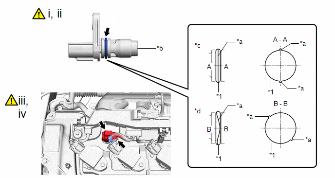
1. INSTALL CAMSHAFT POSITION SENSOR (for Exhaust Side)
|
*1 | O-ring |
- | - |
|
*a | Seam |
*b | Camshaft Position Sensor Tip |
|
*c | OK |
*d | NG |
(1) Perform this procedure only when reusing the camshaft position sensor.
1. Clean the O-ring groove of the camshaft position sensor.
NOTICE:
Make sure the O-ring groove is free of foreign matter.
2. Install a new O-ring to the camshaft position sensor.
NOTICE:
Set the O-ring on the tip of the camshaft position sensor and roll it into the O-ring groove with bare hands to install it.
3. Check if the O-ring is twisted.
HINT:
Check the entire circumference of the seam of the O-ring for twisting.
(2) Apply a light coat of engine oil to the O-ring of the camshaft position sensor.
NOTICE:
If reusing the camshaft position sensor, be sure to inspect the O-ring.
(3) Using an 8 mm socket wrench, install the camshaft position sensor to the cylinder head cover sub-assembly with a new bolt.
Torque:
7.5 N·m {76 kgf·cm, 66 in·lbf}
NOTICE:
- If the camshaft position sensor has been struck or dropped, replace it.
- Make sure that the O-ring is not cracked or moved out of place when installing the camshaft position sensor.
(4) Connect the camshaft position sensor connector.
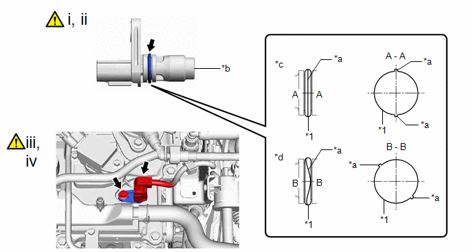
2. INSTALL CAMSHAFT POSITION SENSOR (for Intake Side)
|
*1 | O-ring |
- | - |
|
*a | Seam |
*b | Camshaft Position Sensor Tip |
|
*c | OK |
*d | NG |
(1) Perform this procedure only when reusing the camshaft position sensor.
1. Clean the O-ring groove of the camshaft position sensor.
NOTICE:
Make sure the O-ring groove is free of foreign matter.
2. Install a new O-ring to the camshaft position sensor.
NOTICE:
Set the O-ring on the tip of the camshaft position sensor and roll it into the O-ring groove with bare hands to install it.
3. Check if the O-ring is twisted.
HINT:
Check the entire circumference of the seam of the O-ring for twisting.
(2) Apply a light coat of engine oil to the O-ring of the camshaft position sensor.
NOTICE:
If reusing the camshaft position sensor, be sure to inspect the O-ring.
(3) Using an 8 mm socket wrench, install the camshaft position sensor to the cylinder head cover sub-assembly with a new bolt.
Torque:
7.5 N·m {76 kgf·cm, 66 in·lbf}
NOTICE:
- If the camshaft position sensor has been struck or dropped, replace it.
- Make sure that the O-ring is not cracked or moved out of place when installing the camshaft position sensor.
(4) Connect the camshaft position sensor connector.
3. INSPECT FOR ENGINE OIL LEAK
Click here


