Toyota Corolla Cross: Installation
INSTALLATION
CAUTION / NOTICE / HINT
COMPONENTS (INSTALLATION)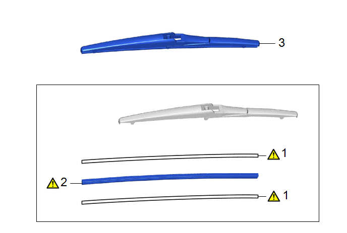
|
Procedure |
Part Name Code |
.png) |
.png) |
.png) |
|
|---|---|---|---|---|---|
|
1 |
WIPER BLADE RUBBER BACKING PLATE |
- |
|
- |
- |
|
2 |
REAR WIPER RUBBER |
85214R |
|
- |
- |
|
3 |
REAR WIPER BLADE |
85242 |
- |
- |
- |
.gif)
PROCEDURE
1. INSTALL WIPER BLADE RUBBER BACKING PLATE

(1) Install the 2 rear wiper rubber backing plates to the rear wiper rubber as shown in the illustration.
NOTICE:
Install the backing plates facing the correct direction.
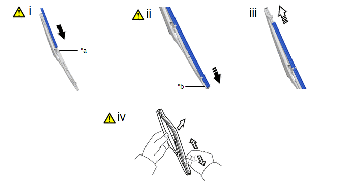
2. INSTALL REAR WIPER RUBBER
|
*a |
Second Claw |
*b |
Stopper |
.png) |
Install in this Direction (1) |
.png) |
Install in this Direction (2) |
(1) Insert the rear wiper rubber with the 2 rear wiper rubber backing plates through the second claw from the front of the rear wiper blade and then push it through each claw until the rear claw.
(2) After pushing the rear wiper rubber through the rear claw, pull it slightly over the rear stopper as shown in the illustration.
(3) Slide the rear wiper rubber through the front claw as shown in the illustration.
(4) Securely engage the rear wiper blade claw to the rear wiper rubber groove as shown in the illustration.
HINT:
- If the front claw of the rear wiper blade is not in the rear wiper rubber groove, grasp the rear wiper rubber and slide it up and down multiple times to insert the claw into the groove.
- Applying a small amount of window washer fluid to the rear wiper rubber can make it easier to insert the claw into the groove.
3. INSTALL REAR WIPER BLADE


