Toyota Corolla Cross: Inspection
INSPECTION
PROCEDURE
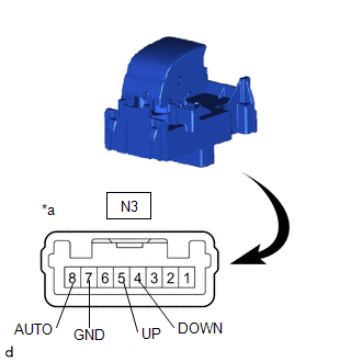
1. INSPECT REAR POWER WINDOW REGULATOR SWITCH ASSEMBLY (for LH Side)
(a) Check the resistance.
| (1) Measure the resistance according to the value(s) in the table below.
Standard Resistance: |
Tester Connection | Condition |
Specified Condition | |
N3-5 (UP) - N3-7 (GND) |
Auto up or up position |
Below 100 Ω | |
N3-4 (DOWN) - N3-7 (GND) |
Auto down or down position |
Below 100 Ω | |
N3-8 (AUTO) - N3-7 (GND) |
Auto up or auto down position |
Below 100 Ω | |
N3-5 (UP) - N3-7 (GND) |
Off | 10 kΩ or higher | |
N3-4 (DOWN) - N3-7 (GND) |
Off | 10 kΩ or higher | |
N3-8 (AUTO) - N3-7 (GND) |
Off | 10 kΩ or higher |
If the result is not as specified, replace the rear power window regulator switch assembly. |
 |
|
*a | Component without harness connected
(Rear Power Window Regulator Switch Assembly) | | |
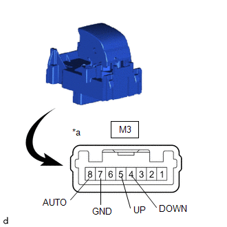
2. INSPECT REAR POWER WINDOW REGULATOR SWITCH ASSEMBLY (for RH Side)
(a) Check the resistance.
| (1) Measure the resistance according to the value(s) in the table below.
Standard Resistance: |
Tester Connection | Condition |
Specified Condition | |
M3-5 (UP) - M3-7 (GND) |
Auto up or up position |
Below 100 Ω | |
M3-4 (DOWN) - M3-7 (GND) |
Auto down or down position |
Below 100 Ω | |
M3-8 (AUTO) - M3-7 (GND) |
Auto up or auto down position |
Below 100 Ω | |
M3-5 (UP) - M3-7 (GND) |
Off | 10 kΩ or higher | |
M3-4 (DOWN) - M3-7 (GND) |
Off | 10 kΩ or higher | |
M3-8 (AUTO) - M3-7 (GND) |
Off | 10 kΩ or higher |
If the result is not as specified, replace the rear power window regulator switch assembly. |
 |
|
*a | Component without harness connected
(Rear Power Window Regulator Switch Assembly) | | |
READ NEXT:
INSTALLATION CAUTION / NOTICE / HINT COMPONENTS (INSTALLATION)
Procedure Part Name Code
1 REAR POWER WINDOW REGULATOR SWITCH ASSEMBLY
84810D -
- -
On-vehicle InspectionON-VEHICLE INSPECTION PROCEDURE
1. INSPECT FRONT WIPER DEICER RELAY (a) Check the resistance.
(1) Measure the resistance according to the value(s) in the table below.
Stan
SEE MORE:
DESCRIPTION The battery ECU assembly monitors its internal operation and will store these DTCs when it detects an internal malfunction.
DTC No. Detection Item
DTC Detection Condition
Trouble Area MIL
Warning Indicate Note
P060687 Hybrid/EV Battery Energy Con
DESCRIPTION If the air inlet mode cannot be changed between recirculation/fresh or exhaust gas odors can be smelled even though recirculation mode is selected, the following factors may be the cause.
Symptom Factor
Air inlet mode cannot be changed between recirculation/fresh


