Toyota Corolla Cross: Inspection
INSPECTION
PROCEDURE
1. INSPECT CANISTER (CHARCOAL CANISTER ASSEMBLY)
(a) Visually check the canister (charcoal canister assembly).
(1) Visually check the canister (charcoal canister assembly) for cracks or damage.
If cracks or damage is found, replace the canister (charcoal canister assembly).
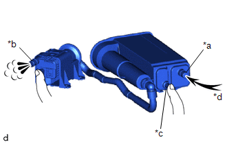
(b) Check canister (charcoal canister assembly) operation.
| (1) With the purge line port closed, blow 0.5 kPa (0.005 kgf/cm2, 0.1 psi) of air into the vent line port, and check that air flows from the airline port. If the result is not as specified, replace the canister (charcoal canister assembly). |
|
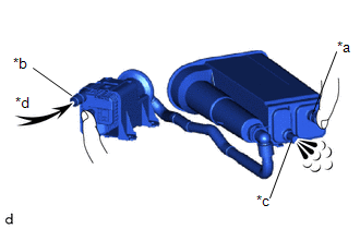
| (2) With the vent line port closed, blow 0.5 kPa (0.005 kgf/cm2, 0.1 psi) of air into the air line port, and check that air flows from the purge line port. If the result is not as specified, replace the canister (charcoal canister assembly). |
|
(c) Check for air leaks.
|
(1) Connect a pressure gauge to the vent line port. |
|
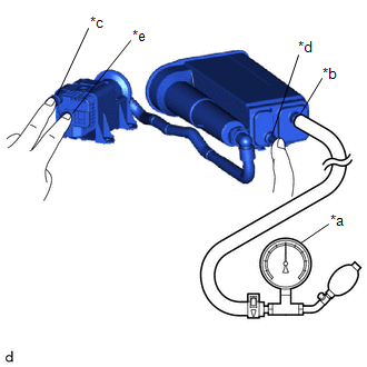
(2) With the purge line port, airline port and leak detection pump sub-assembly connector closed, apply 20 kPa (150 mmHg, 5.91 in. Hg) of pressurized air into the vent line port, then confirm that pressure is maintained for 1 minute.
If the result is not as specified, replace the canister (charcoal canister assembly).
(d) Check the leak detection pump sub-assembly.
| (1) Connect a positive (+) battery lead to terminal 5 and a negative (-) battery lead to terminal 1. |
|
.png)
(2) Check that a clicking sound is heard from the leak detection pump sub-assembly.
If the result is not as specified, replace the leak detection pump sub-assembly.


