Toyota Corolla Cross: Inspection
INSPECTION
PROCEDURE
1. INSPECT SHIFT LEVER POSITION SENSOR
|
(a) Measure the resistance according to the value(s) in the table below.
Standard Resistance:
|
Tester Connection
|
Condition
|
Specified Condition
|
|
7 (+B) - 3 (PR)
|
Shift lever in P
|
Below 1 Ω
|
|
7 (+B) - 4 (PNB)
|
Below 1 Ω
|
|
7 (+B) - 8 (P)
|
Below 1 Ω
|
|
7 (+B) - 1 (DB1), 2 (N), 6 (DB2) or 9 (R)
|
Shift lever in P
|
10 kΩ or higher
|
|
7 (+B) - 3 (PR)
|
Shift lever in R
|
Below 1 Ω
|
|
7 (+B) - 9 (R)
|
Below 1 Ω
|
|
7 (+B) - 1 (DB1), 2 (N), 4 (PNB), 6 (DB2) or 8 (P)
|
Shift lever in R
|
10 kΩ or higher
|
|
7 (+B) - 2 (N)
|
Shift lever in N
|
Below 1 Ω
|
|
7 (+B) - 4 (PNB)
|
Below 1 Ω
|
|
7 (+B) - 1 (DB1), 3 (PR), 6 (DB2), 8 (P) or 9 (R)
|
Shift lever in N
|
10 kΩ or higher
|
|
7 (+B) - 1 (DB1)
|
Shift lever in D
|
Below 1 Ω
|
|
7 (+B) - 6 (DB2)
|
Below 1 Ω
|
|
7 (+B) - 2 (N), 3 (PR), 4 (PNB), 8 (P) or 9 (R)
|
Shift lever in D
|
10 kΩ or higher
|
|
7 (+B) - 1 (DB1)
|
Shift lever in B
|
Below 1 Ω
|
|
7 (+B) - 4 (PNB)
|
Below 1 Ω
|
|
7 (+B) - 6 (DB2)
|
Below 1 Ω
|
|
7 (+B) - 2 (N), 3 (PR), 8 (P) or 9 (R)
|
Shift lever in B
|
10 kΩ or higher
|
HINT:
The shift lever position sensor connector (shift lever position sensor
side) does not have a terminal 5.
If the result is not as specified, replace the shift lever position sensor.
|
|
|
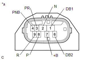
*a
|
Component without harness connected
(Shift Lever Position Sensor)
|
|
|
READ NEXT:
ADJUSTMENT
PROCEDURE
1. SECURE VEHICLE
(a) Fully apply the parking brake and chock a wheel.
CAUTION:
Make sure to apply the parking brake and chock a wheel before performing
this procedure.
INSTALLATION
CAUTION / NOTICE / HINT
COMPONENTS (INSTALLATION)
Procedure
Part Name Code
1
SHIFT LEVER POSITION SENSOR S
SEE MORE:
DESCRIPTION
The skid control ECU (brake actuator assembly) communicates
with the following ECUs and sensors via CAN communication.
ECM
Yaw rate and acceleration sensor (airbag ECU assembly)
Steering sensor
Power steering ECU assembly
Main body ECU (multiplex network body ECU)
A
INSTALLATION CAUTION / NOTICE / HINT COMPONENTS (INSTALLATION)
Procedure Part Name Code
1 REAR POWER WINDOW REGULATOR SWITCH ASSEMBLY
84810D -
- -
2 REAR POWER WINDOW REGULATOR SWITCH ASSEMBLY WITH REAR DOOR ARMREST BASE PANEL
- -
-


