Toyota Corolla Cross: Inspection
INSPECTION
PROCEDURE
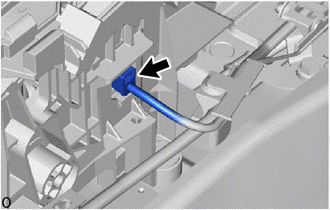
1. INSPECT SHIFT LOCK CONTROL ECU
HINT:
If the results of the following inspections are as specified but a malfunction
has occurred, replace the shift lock control unit assembly.
(a) Inspect wire harness:
|
(1) Disconnect the shift lock control ECU connector.
|
|
|
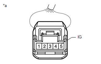
(2) Measure the voltage according to the value(s) in the table below.
Standard Voltage:
|
Tester Connection
|
Condition
|
Specified Condition
|
|
5 (IG) - Body ground
|
Ignition switch ON
|
11 to 14 V
|
|
Ignition switch off
|
Below 1 V
|
If the result is not as specified, repair or replace the shift lock control
ECU wire harness.
|
|
|
*a
|
Front view of wire harness connector
(to Shift Lock Control ECU)
|
|
|
|
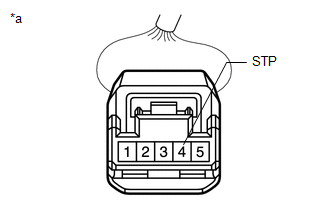
(3) Measure the voltage according to the value(s) in the table below.
Standard Voltage:
|
Tester Connection
|
Condition
|
Specified Condition
|
|
4 (STP) - Body ground
|
Ready ON, brake pedal depressed
|
11 to 14 V
|
|
Ready ON, brake pedal released
|
Below 1 V
|
If the result is not as specified, repair or replace the wire harness
or connector or replace the hybrid vehicle control ECU assembly.
|
|
|
*a
|
Front view of wire harness connector
(to Shift Lock Control ECU)
|
|
|
|
(4) Measure the resistance according to the value(s) in the table below.
Standard Resistance:
|
Tester Connection
|
Condition
|
Specified Condition
|
|
1 (E) - Body ground
|
Always
|
Below 1 Ω
|
If the result is not as specified, repair or replace the shift lock control
ECU wire harness.
|
.png) |
|
*a
|
Front view of wire harness connector
(to Shift Lock Control ECU)
|
|
|
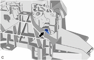
(b) Inspect shift lock solenoid:
|
(1) Disconnect the shift lock solenoid connector.
|
|
|
(2) Measure the resistance according to the value(s) in the table below.
Standard Resistance:
|
Tester Connection
|
Condition
|
Specified Condition
|
|
4 (P) - 3 (E2)
|
Shift lever in P
|
10 kΩ or higher
|
|
Shift lever not in P
|
Below 1 Ω
|
If the result is not as specified, replace the shift lock control unit
assembly.
|
.png) |
|
*a
|
Front view of wire harness connector
(to Shift Lock Solenoid)
|
|
|
|
(3) Measure the resistance according to the value(s) in the table below.
Standard Resistance:
|
Tester Connection
|
Condition
|
Specified Condition
|
|
1 (SLS+) - 2 (SLS-)
|
Always
|
112 Ω
|
If the result is not as specified, replace the shift lock control unit
assembly.
|
.png) |
|
*a
|
Front view of wire harness connector
(to Shift Lock Solenoid)
|
|
|
READ NEXT:
REASSEMBLY
CAUTION / NOTICE / HINT
COMPONENTS (REASSEMBLY)
Procedure
Part Name Code
1
SHIFT LEVER HOUSING BRACKET SUB-A
INSTALLATION
CAUTION / NOTICE / HINT
COMPONENTS (INSTALLATION)
Procedure
Part Name Code
1
TRANSMISSION FLOOR SHIFT ASSE
Removal
REMOVAL
CAUTION / NOTICE / HINT
COMPONENTS (REMOVAL)
Procedure
Part Name Code
1
SHIFT LEVER KNOB SUB-ASSEMBL
SEE MORE:
DESCRIPTION These DTCs are stored when the CAN communication system is malfunctioning.
DTC No. Detection Item
DTC Detection Condition Trouble Area
Memory U010087
Lost Communication with ECM/PCM "A" Missing Message
Diagnosis Condition:
IG voltage 8.5 V or
PARTS LOCATION ILLUSTRATION
*A for Gasoline Model
- -
*1 REAR DOOR COURTESY LIGHT ASSEMBLY RH
*2 REAR DOOR COURTESY LIGHT ASSEMBLY LH
*3 ECM
- - ILLUSTRATION
*A for HEV Model
- -
*1 COMBINATION METER ASSEMBLY