Toyota Corolla Cross: Engine Hood Courtesy Switch
Removal
REMOVAL
CAUTION / NOTICE / HINT
COMPONENTS (REMOVAL)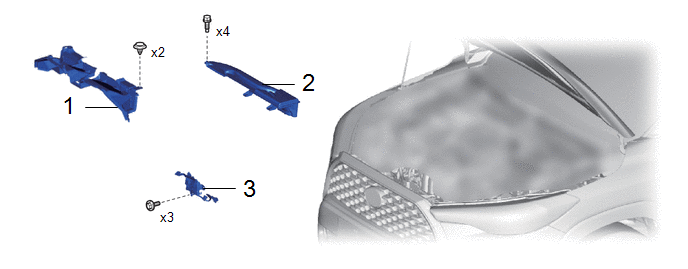
|
Procedure | Part Name Code |
.png) |
.png) |
 |
|---|---|---|---|---|---|
|
1 | NO. 1 RADIATOR TO SUPPORT SEAL |
16561C | - |
- | - |
|
2 | INLET NO. 1 AIR CLEANER |
17751 | - |
- | - |
|
3 | HOOD LOCK ASSEMBLY WITH COURTESY LIGHT SWITCH |
53510G | - |
- | - |
PROCEDURE
1. REMOVE NO. 1 RADIATOR TO SUPPORT SEAL
Click here
.gif)
2. REMOVE INLET NO. 1 AIR CLEANER
Click here
3. REMOVE HOOD LOCK ASSEMBLY WITH COURTESY LIGHT SWITCH
Inspection
INSPECTION
PROCEDURE
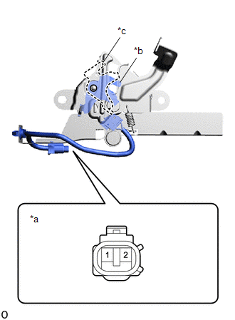
1. INSPECT ENGINE HOOD COURTESY SWITCH (HOOD LOCK ASSEMBLY WITH COURTESY LIGHT SWITCH)
| (a) Check the resistance. (1) Measure the resistance according to the value(s) in the table below. Standard Resistance:
If the resistance is not as specified, replace the engine hood courtesy switch (hood lock assembly with courtesy light switch). |
|
Installation
INSTALLATION
CAUTION / NOTICE / HINT
COMPONENTS (INSTALLATION)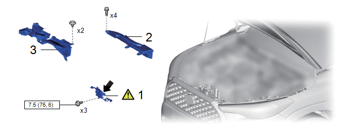
|
Procedure | Part Name Code |
.png) |
.png) |
 |
|---|---|---|---|---|---|
|
1 | HOOD LOCK ASSEMBLY WITH COURTESY LIGHT SWITCH |
53510G |
|
- | - |
|
2 | INLET NO. 1 AIR CLEANER |
17751 | - |
- | - |
|
3 | NO. 1 RADIATOR TO SUPPORT SEAL |
16561C | - |
- | - |
.png) |
N*m (kgf*cm, ft.*lbf): Specified torque |
.png) |
MP grease |
PROCEDURE
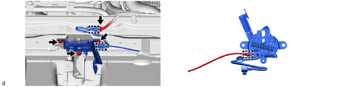
1. INSTALL HOOD LOCK ASSEMBLY WITH COURTESY LIGHT SWITCH

.png) |
MP Grease | - |
- |
(1) Apply MP grease to the sliding parts of the hood lock with courtesy light switch assembly.
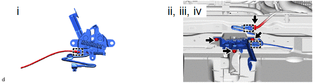
(1) Engage the guide and connect the hood lock control cable assembly to the hood lock with courtesy light switch assembly.
(2) Install the hood lock with courtesy light switch assembly with the 3 bolts.
Torque:
7.5 N·m {76 kgf·cm, 66 in·lbf}
(3) Engage the clamps.
(4) Connect the connector.
2. INSTALL INLET NO. 1 AIR CLEANER
Click here
.gif)
3. INSTALL NO. 1 RADIATOR TO SUPPORT SEAL


