Toyota Corolla Cross: Electronic Brake Booster Input Stroke Sensor "A" Circuit Short to Ground (C127A11,...,C128F64)
DESCRIPTION
The relative displacement sensor is built into the brake booster with master cylinder assembly.
When the relative displacement sensor inside the electric brake booster (brake booster with master cylinder assembly) meets the detection conditions, this DTC is stored.
|
DTC No. |
Detection Item |
DTC Detection Condition |
Trouble Area |
MIL |
DTC Output from |
Note |
|---|---|---|---|---|---|---|
|
C127A11 |
Electronic Brake Booster Input Stroke Sensor "A" Circuit Short to Ground |
Open in relative displacement sensor (brake booster with master cylinder assembly) signal circuit for 0.1 seconds or more. |
|
Comes on |
Brake Booster |
|
|
C127A15 |
Electronic Brake Booster Input Stroke Sensor "A" Circuit Short to Battery or Open |
Short in relative displacement sensor (brake booster with master cylinder assembly) signal circuit for 0.1 seconds or more. |
|
Comes on |
Brake Booster |
|
|
C127A16 |
Electronic Brake Booster Input Stroke Sensor "A" Circuit Voltage Below Threshold |
Relative displacement sensor (brake booster with master cylinder assembly) output value is -3.9 mm or less for 0.2 seconds or more. |
|
Comes on |
Brake Booster |
|
|
C127A17 |
Electronic Brake Booster Input Stroke Sensor "A" Circuit Voltage Above Threshold |
Relative displacement sensor (brake booster with master cylinder assembly) output value is 3.4 mm or more for 0.2 seconds or more. |
|
Comes on |
Brake Booster |
|
|
C127A23 |
Electronic Brake Booster Input Stroke Sensor "A" Signal Stuck Low |
Relative displacement sensor (brake booster with master cylinder assembly) output value is less than 0.6 mm for 0.3 seconds or more. |
|
Comes on |
Brake Booster |
|
|
C127A24 |
Electronic Brake Booster Input Stroke Sensor "A" Signal Stuck High |
While driving at a vehicle speed of 3 km/h (2 mph) or more, the brake pedal stroke distance is between 0.6 mm and 1.5 mm for 60 seconds or more. |
|
Comes on |
Brake Booster |
|
|
C127A64 |
Electronic Brake Booster Input Stroke Sensor "A" Signal Plausibility Failure |
Relative displacement sensor (brake booster with master cylinder assembly) output signal interrupted for 0.1 seconds or more. |
|
Comes on |
Brake Booster |
|
|
C127A86 |
Electronic Brake Booster Input Stroke Sensor "A" Signal (some circuit quantity, reported via serial data) Invalid |
Relative displacement sensor (brake booster with master cylinder assembly) malfunction is detected for 1 second or more. |
|
Comes on |
Brake Booster |
|
|
C127A96 |
Electronic Brake Booster Input Stroke Sensor "A" Component Internal Failure |
Relative displacement sensor (brake booster with master cylinder assembly) internal malfunction is detected for 0.1 seconds or more. |
|
Comes on |
Brake Booster |
|
|
C127F1C |
Electronic Brake Booster Input Stroke Sensor Supply Voltage Circuit Voltage Out of Range |
Relative displacement sensor (brake booster with master cylinder assembly) power source voltage (VSK) is less than 4.8 V or more than 5.18 V for 0.08 seconds or more. |
|
Comes on |
Brake Booster |
|
|
C128A11 |
Electronic Brake Booster Input Stroke Sensor "B" Circuit Short to Ground |
Open in relative displacement sensor (brake booster with master cylinder assembly) signal circuit for 0.2 seconds or more. |
|
Comes on |
Brake Booster |
|
|
C128A15 |
Electronic Brake Booster Input Stroke Sensor "B" Circuit Short to Battery or Open |
Short in relative displacement sensor (brake booster with master cylinder assembly) signal circuit for 0.2 seconds or more. |
|
Comes on |
Brake Booster |
|
|
C128A64 |
Electronic Brake Booster Input Stroke Sensor "B" Signal Plausibility Failure |
Relative displacement sensor (brake booster with master cylinder assembly) operation failure is detected for 0.2 seconds or more. |
|
Comes on |
Brake Booster |
|
|
C128F64 |
Electronic Brake Booster Input Stroke Sensor "A" / "B" Signal Plausibility Failure |
Difference between change amounts of relative displacement sensor (brake booster with master cylinder assembly) output 1 (SKS1) and relative displacement sensor (brake booster with master cylinder assembly) output 2 (SKS2) is abnormally large for 0.2 seconds or more. |
|
Comes on |
Brake Booster |
|
MONITOR DESCRIPTION
C127A (Case 1):- When the electronically controlled brake system is starting and a differential travel sensor invalid state continues for a certain amount of time, the electric brake booster (brake booster with master cylinder assembly) illuminates the MIL and stores this DTC.
- When the electronically controlled brake system is operating or shutting down and a differential travel sensor malfunction is detected, the electric brake booster (brake booster with master cylinder assembly) illuminates the MIL and stores this DTC.
- When the vehicle is being driven at a certain speed or more, the electronically controlled brake system is operating, and the output value of the differential travel sensor is outside of a certain range for a certain amount of time, the electric brake booster (brake booster with master cylinder assembly) illuminates the MIL and stores this DTC.
- When the electronically controlled brake system is operating and the output value of the differential travel sensor is a certain value or more, the electric brake booster (brake booster with master cylinder assembly) illuminates the MIL and stores this DTC.
- When the electronic electronically controlled brake system is not operating and the output value of the differential travel sensor is less than a certain value, the electric brake booster (brake booster with master cylinder assembly) illuminates the MIL and stores this DTC.
- When the electronically controlled brake system is operating and the output value of the differential travel sensor is a certain value or less, the electric brake booster (brake booster with master cylinder assembly) illuminates the MIL and stores this DTC.
- When the vehicle is being driven at a certain speed or more, the electronically controlled brake system is operating, and the output value of the differential travel sensor is outside of a certain range for the current trip and previous trip for a certain amount of time, the electric brake booster (brake booster with master cylinder assembly) illuminates the MIL and stores this DTC.
- When the vehicle is being driven at less than a certain speed, the electronically controlled brake system is operating, and the output value of the differential travel sensor is outside of a certain range for the current trip and previous trip for a certain amount of time, the electric brake booster (brake booster with master cylinder assembly) illuminates the MIL and stores this DTC.
- When the electronically controlled brake system is operating or shutting down and a differential travel sensor invalid state is detected, the electric brake booster (brake booster with master cylinder assembly) illuminates the MIL and stores this DTC.
- When the electronically controlled brake system is operating or shutting down and an open in the signal circuit of the differential travel sensor is detected, the electric brake booster (brake booster with master cylinder assembly) illuminates the MIL and stores this DTC.
- When the electronically controlled brake system is operating or shutting down and a short in the signal circuit of the differential travel sensor is detected, the electric brake booster (brake booster with master cylinder assembly) illuminates the MIL and stores this DTC.
- When the electronically controlled brake system is operating or shutting down and the power supply voltage of the differential travel sensor is outside of a certain range, the electric brake booster (brake booster with master cylinder assembly) illuminates the MIL and stores this DTC.
- When the electronically controlled brake system is operating or shutting down and the PWM duty cycle or PWM operation frequency of the differential travel sensor is outside of a certain range, the electric brake booster (brake booster with master cylinder assembly) illuminates the MIL and stores this DTC.
- When the electronically controlled brake system is operating and the difference between output 1 and output 2 of the differential travel sensor exceeds a certain value, the electric brake booster (brake booster with master cylinder assembly) illuminates the MIL and stores this DTC.
MONITOR STRATEGY
|
Related DTCs |
C127A (Case 1): Relative displacement sensor time out C127A (Case 2): Relative displacement sensor internal failure (sent) C127B (Case 1): Relative displacement sensor offset monitoring (high-suspicious) C127B (Case 2): Relative displacement sensor range monitoring (channel 1 high) C127B (Case 3): Relative displacement sensor offset monitoring (low) C127B (Case 4): Relative displacement sensor range monitoring (channel 1 low) C127B (Case 5): Relative displacement sensor offset monitoring (high) C127B (Case 6): Relative displacement sensor range monitoring (channel 2 high) C127B (Case 7): Relative displacement sensor range monitoring (channel 2 low) C127B (Case 8): Relative displacement sensor communication failure (sent) C127C: Relative displacement sensor line monitoring (sent-low) C127D: Relative displacement sensor line monitoring (sent-high) C127F: Relative displacement sensor supply line monitor C128B: Relative displacement sensor PWM monitor C128C: Relative displacement sensor line monitoring (PWM-low) C128D: Relative displacement sensor line monitoring (PWM-high) C128F: Relative displacement sensor rationality monitoring |
|
Required Sensors/Components(Main) |
Electric brake booster (brake booster with master cylinder assembly) |
|
Required Sensors/Components(Related) |
Electric brake booster (brake booster with master cylinder assembly) Speed sensor |
|
Frequency of Operation |
Continuous: C127B (Case 1 to 8), C127C, C127D, C127F, C128B, C128C, C128D, C128F During initial checking: C127A (Case 1 and 2) |
|
Duration |
0.08 seconds: C127F 0.1 seconds: C127A (Case 2), C127B (Case 8), C127C and C127D 0.2 seconds: C127B (Case 2, 4, 6 and 7), C128B, C128C, C128D and C128F 0.3 seconds: C127B (Case 3) 1 second: C127A (Case 1) 60 seconds: C127B (Case 1 and 5-1) 300 seconds: C127B (Case 5-2) |
|
MIL Operation |
Immediately: C127A (Case 1 and 2) 2 driving cycles: C127B (Case 1, 2, 3, 4, 5, 6, 7 and 8), C127C, C127D, C127F, C128B, C128C, C128D and C128F |
|
Sequence of Operation |
None |
TYPICAL ENABLING CONDITIONS
|
Monitor runs whenever the following DTCs are not stored |
TMC's intellectual property |
|
Other conditions belong to TMC's intellectual property |
- |
TYPICAL MALFUNCTION THRESHOLDS
|
TMC's intellectual property |
- |
COMPONENT OPERATING RANGE
|
TMC's intellectual property |
- |
CONFIRMATION DRIVING PATTERN
NOTICE:
When performing the normal judgment procedure, make sure that the driver door is closed and is not opened at any time during the procedure.
HINT:
- After repair has been completed, clear the DTC and then check that the vehicle has returned to normal by performing the following All Readiness check procedure.
- When clearing the permanent DTCs, refer to the "CLEAR PERMANENT DTC" procedure.
- Connect the GTS to the DLC3.
- Turn the ignition switch to ON and turn the GTS on.
- Clear the DTCs (even if no DTCs are stored, perform the clear DTC procedure).
- Turn the ignition switch off.
- Turn the ignition switch to ON (READY) and turn the GTS on.
- Wait for 1 second or more. [*]
HINT:
[*]: Normal judgment procedure.
The normal judgment procedure is used to complete DTC judgment and also used when clearing permanent DTCs.
- Enter the following menus: Chassis / Brake Booster / Utility / All Readiness.
- Check the DTC judgment result.
HINT:
- If the judgment result shows NORMAL, the system is normal.
- If the judgment result shows ABNORMAL, the system has a malfunction.
- If the judgment result shows INCOMPLETE, perform driving pattern again.
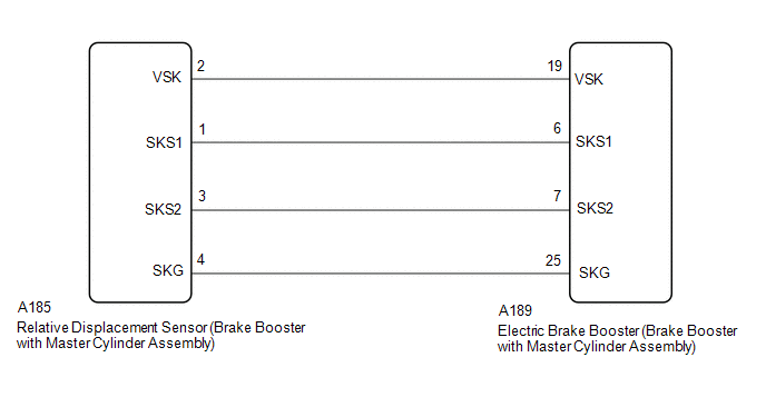
WIRING DIAGRAM
PROCEDURE
|
1. |
CHECK HARNESS AND CONNECTOR |
(a) Turn the ignition switch off.
(b) Make sure that there is no looseness at the locking part and the connecting part of the connectors.
OK:
The connector is securely connected.
(c) Disconnect the A189 electric brake booster (brake booster with master cylinder assembly) connector.
(d) Disconnect the A185 relative displacement sensor (brake booster with master cylinder assembly) connector.
(e) Check both the connector case and the terminals for deformation and corrosion.
OK:
No deformation or corrosion.
(f) Measure the resistance according to the value(s) in the table below.
Standard Resistance:
|
Tester Connection |
Condition |
Specified Condition |
|---|---|---|
|
A189-19 (VSK) - A185-2 (VSK) |
Always |
Below 1 Ω |
|
A189-19 (VSK) or A185-2 (VSK) - Body ground and other terminals |
Always |
10 kΩ or higher |
|
A189-6 (SKS1) - A185-1 (SKS1) |
Always |
Below 1 Ω |
|
A189-6 (SKS1) or A185-1 (SKS1) - Body ground and other terminals |
Always |
10 kΩ or higher |
|
A189-7 (SKS2) - A185-3 (SKS2) |
Always |
Below 1 Ω |
|
A189-7 (SKS2) or A185-3 (SKS2) - Body ground and other terminals |
Always |
10 kΩ or higher |
|
A189-25 (SKG) - A185-4 (SKG) |
Always |
Below 1 Ω |
|
A189-25 (SKG) or A185-4 (SKG) - Body ground and other terminals |
Always |
10 kΩ or higher |
| OK | .gif)
|
REPLACE BRAKE BOOSTER WITH MASTER CYLINDER ASSEMBLY |
| NG |
|
REPAIR OR REPLACE HARNESS OR CONNECTOR |


