Toyota Corolla Cross: Electric Parking Brake System AUTO Function Circuit
DESCRIPTION
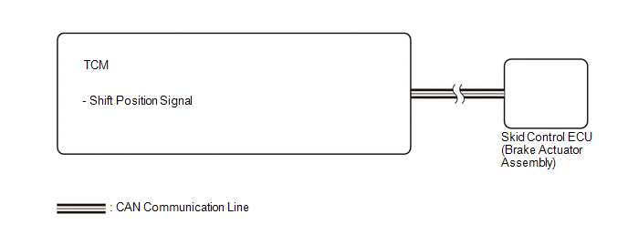
The skid control ECU (brake actuator assembly) receives shift position signals from the TCM via CAN communication to control the electric parking brake system AUTO function (shift-linked function).
The electric parking brake system AUTO function (shift-linked function) is automatically disabled when the ignition switch is ON, the brake pedal is depressed and the shift lever is moved out of P. Then, if the shift lever is moved to P, the AUTO function (shift-linked function) automatically operates to apply the electric parking brake.
WIRING DIAGRAM
CAUTION / NOTICE / HINT
NOTICE:
- The AUTO function (shift-linked function) will not be automatically disabled when the ignition switch is ON, the brake pedal is depressed and the shift lever is moved out from P if the electric parking brake switch assembly is moved to the engage side. The AUTO function (shift-linked function) will not automatically operate to apply the electric parking brake when the shift lever is moved to P if the electric parking brake switch assembly is moved to the release side.
- The electric parking brake may still operate up to 20 seconds after the ignition switch is turned off. Before disconnecting connectors or fuses, turn the ignition switch off and wait 20 seconds or more.
- After replacing the skid control ECU (brake actuator assembly), perform
acceleration sensor zero point calibration and store system information
memorization.
Click here
.gif)
- When replacing the skid control ECU (brake actuator assembly), operate the electric parking brake switch (electric parking brake switch assembly) as the parking brake indicator light blinks (red) when the ignition switch is first turned ON.
PROCEDURE
|
1. |
CHECK DTC (CONTINUOUSLY VARIABLE TRANSAXLE SYSTEM) |
(a) Check for DTCs.
Powertrain > Transmission > Trouble Codes|
Result |
Proceed to |
|---|---|
|
DTC is not output |
A |
|
DTC is output (for 2WD) |
B |
|
DTC is output (for AWD) |
C |
| A | .gif)
|
REPLACE SKID CONTROL ECU (BRAKE ACTUATOR ASSEMBLY) |
| B |
|
GO TO CONTINUOUSLY VARIABLE TRANSAXLE SYSTEM |
| C |
|
GO TO CONTINUOUSLY VARIABLE TRANSAXLE SYSTEM |


