Toyota Corolla Cross: Components
COMPONENTS
ILLUSTRATION
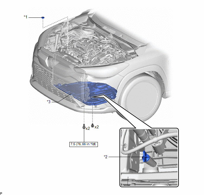
|
*1
|
RESERVE TANK CAP
|
*2
|
DRAIN COCK PLUG
|
|
*3
|
NO. 1 ENGINE UNDER COVER ASSEMBLY
|
-
|
-
|
.png) |
N*m (kgf*cm, ft.*lbf): Specified torque
|
-
|
-
|
READ NEXT:
REPLACEMENT
CAUTION / NOTICE / HINT
CAUTION:
To avoid the danger of being burned, do not remove the reserve tank cap or drain
cock plug while the coolant (for inverter) is still hot. Pressurized,
Components
COMPONENTS
ILLUSTRATION
*1
OIL FILTER SUB-ASSEMBLY
*2
OIL FILLER CAP ASSEMBLY
*3
GASKET
*4
Removal
REMOVAL
CAUTION / NOTICE / HINT
COMPONENTS (REMOVAL)
Procedure
Part Name Code
1
IGNITION COIL ASSEMBLY
SEE MORE:
PARTS LOCATION ILLUSTRATION
*1 HEADLIGHT UNIT ASSEMBLY LH
*2 HEADLIGHT UNIT ASSEMBLY RH
*3 SIDE TURN SIGNAL LIGHT ASSEMBLY LH
*4 SIDE TURN SIGNAL LIGHT ASSEMBLY RH
*5 MILLIMETER WAVE RADAR SENSOR ASSEMBLY
*6 FORWARD RECOGNITION CAMERA
*7 OUTER
DESCRIPTION Refer to the description for DTC P0AD911.
Click here
DTC No. Detection Item
DTC Detection Condition
Trouble Area MIL
Warning Indicate Note
P0ADD15 Hybrid/EV Battery Negative Contactor Circuit Short to Auxiliary Battery or Open
Open or



