Toyota Corolla Cross: Brake System Control Module "A" System Voltage System Voltage High (C137BA3)
DESCRIPTION
If a malfunction is detected in the power supply circuit, the skid control ECU (brake actuator assembly) stores this DTC and the fail-safe function prohibits ABS operation.
This DTC is stored when the +BS terminal voltage deviates due to a malfunction in a power supply or charging system circuit such as the auxiliary battery or alternator circuit, etc.
|
DTC No. |
Detection Item |
DTC Detection Condition |
Trouble Area |
|---|---|---|---|
|
C137BA3 |
Brake System Control Module "A" System Voltage System Voltage High |
+BS terminal voltage is more than 16.5 V for 1 second or more. |
|
WIRING DIAGRAM
Refer to DTC C117A49
Click here .gif)
CAUTION / NOTICE / HINT
NOTICE:
- Inspect the fuses for circuits related to this system before performing the following procedure.
- Before performing troubleshooting, make sure to confirm that the auxiliary
battery voltage is normal.
Click here
PROCEDURE
|
1. |
CHECK HARNESS AND CONNECTOR (POWER SOURCE TERMINAL) |
|
(a) Make sure that there is no looseness at the locking part and the connecting part of the connector. OK: The connector is securely connected. |
|
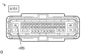
(b) Disconnect the A151 skid control ECU (brake actuator assembly) connector.
(c) Check both the connector case and the terminals for deformation and corrosion.
OK:
No deformation or corrosion.
(d) Measure the voltage according to the value(s) in the table below.
Standard Voltage:
|
Tester Connection |
Condition |
Specified Condition |
|---|---|---|
|
A151-30 (+BS) - Body ground |
Always |
11 to 14 V |
| OK | .gif)
|
REPLACE BRAKE ACTUATOR ASSEMBLY |
| NG |
|
REPAIR OR REPLACE HARNESS OR CONNECTOR |
READ NEXT:
 Stop Lamp Relay Actuator Stuck On (C13807E)
DESCRIPTION
When any of the following conditions are met, the skid control
ECU (brake actuator assembly) sets the drive output (STPO) ON which operates the
stop light control relay (stop light sw
Stop Lamp Relay Actuator Stuck Off (C13807F)
DESCRIPTION
Refer to DTC C13807E.
Click here
DTC No.
Detection Item
DTC Detection Condition
Trouble Area
C13807F
Stop Lamp
Brake Pressure Control Solenoid "A" Control Circuit Short to Battery (C13C012,...,C13C949)
DESCRIPTION
The ABS solenoid relay and master cylinder cut solenoid valves
are built into the brake actuator assembly.
Depending on the operating conditions, the master cylinder cut
solenoid val
SEE MORE:
 Installation
INSTALLATION CAUTION / NOTICE / HINT COMPONENTS (INSTALLATION)
Procedure Part Name Code
1 TRANSPONDER KEY ECU ASSEMBLY
89780 -
- -
2 AIR CONDITIONER UNIT ASSEMBLY
- -
- -
3 PERFORM CODE REGISTRATION
-
"E" Camshaft Position Actuator Bank 1 Signal Invalid (P136629)
DESCRIPTION Refer to DTC P001001. Click here
DTC No. Detection Item
DTC Detection Condition Trouble Area
MIL Note
P136629 "E" Camshaft Position Actuator Bank 1 Signal Invalid
Malfunction in diagnostic signal (VTM) of cam timing control motor with EDU assembl
