Toyota Corolla Cross: Ambient Temperature Sensor
Removal
REMOVAL
CAUTION / NOTICE / HINT
COMPONENTS (REMOVAL)

|
Procedure | Part Name Code |
.png) |
.png) |
.png) |
|
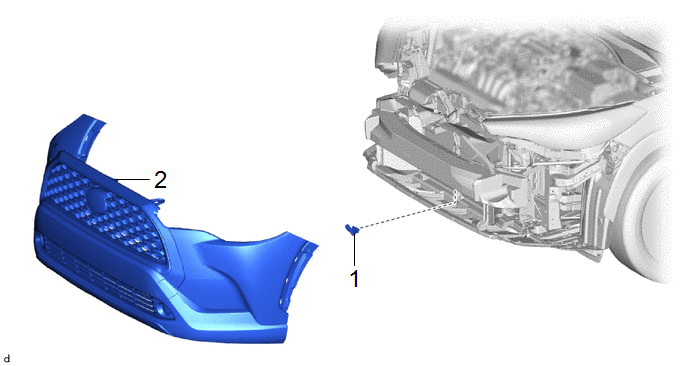
1 | FRONT BUMPER ASSEMBLY |
- | - |
- | - |
|
2 | THERMISTOR ASSEMBLY |
88790B | - |
- | - |
PROCEDURE
1. REMOVE FRONT BUMPER ASSEMBLY
- except Sport Package:
Click here .gif)
- for Sport Package:
Click here
2. REMOVE THERMISTOR ASSEMBLY

Inspection
INSPECTION
PROCEDURE
1. INSPECT THERMISTOR ASSEMBLY
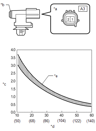
(a) Check the resistance.
| (1) Measure the resistance according to the value(s) in the table below.
Standard Resistance: |
Tester Connection | Condition |
Specified Condition | |
A3-1 - A3-2 | 10°C (50°F) |
3.00 to 3.73 kΩ | | A3-1 - A3-2 |
15°C (59°F) | 2.45 to 2.88 kΩ | |
A3-1 - A3-2 | 20°C (68°F) |
1.95 to 2.30 kΩ | | A3-1 - A3-2 |
25°C (77°F) | 1.60 to 1.80 kΩ | |
A3-1 - A3-2 | 30°C (86°F) |
1.28 to 1.47 kΩ | | A3-1 - A3-2 |
35°C (95°F) | 1.00 to 1.22 kΩ | |
A3-1 - A3-2 | 40°C (104°F) |
0.80 to 1.00 kΩ | | A3-1 - A3-2 |
45°C (113°F) | 0.65 to 0.85 kΩ | |
A3-1 - A3-2 | 50°C (122°F) |
0.50 to 0.70 kΩ | | A3-1 - A3-2 |
55°C (131°F) | 0.44 to 0.60 kΩ | |
A3-1 - A3-2 | 60°C (140°F) |
0.36 to 0.50 kΩ |
NOTICE:
- Hold the sensor only by its connector. Touching the sensing portion may change the resistance value.
- When measuring, the sensor temperature must be the same as the ambient temperature.
HINT: As the temperature increases, the resistance decreases (see the graph).
If the result is not as specified, replace the thermistor assembly. |
 |
|
*a | Component without harness connected
(Thermistor Assembly) | |
*b | Sensing Portion | |
*c | Resistance (kΩ) | |
*d | Temperature (°C (°F)) | |
*e | Allowable Range | | |
Installation
INSTALLATION
CAUTION / NOTICE / HINT
COMPONENTS (INSTALLATION)
|
Procedure | Part Name Code |
.png) |
.png) |
.png) |
|
1 | THERMISTOR ASSEMBLY |
88790B | - |
- | - |
|
2 | FRONT BUMPER ASSEMBLY |
- | - |
- | - |
PROCEDURE
1. INSTALL THERMISTOR ASSEMBLY
2. INSTALL FRONT BUMPER ASSEMBLY
- except Sport Package:
Click here .gif)
- for Sport Package:
Click here
READ NEXT:
REMOVAL CAUTION / NOTICE / HINT COMPONENTS (REMOVAL)
Procedure Part Name Code
1 AIR CONDITIONER UNIT ASSEMBLY
- -
- -
2 NO. 2 AIR DUCT
DISASSEMBLY CAUTION / NOTICE / HINT COMPONENTS (DISASSEMBLY)
Procedure Part Name Code
1 AIR FILTER COVER PLATE
88899M -
- -
2 CLEAN AIR
SEE MORE:
DESCRIPTION Refer to DTC P019011. Click here
DTC No. Detection Item
DTC Detection Condition Trouble Area
MIL Note
P01902A Fuel Rail Pressure Sensor "A" Signal Stuck in Range
When target high pressure side fuel pressure changes, the change in fuel pressure se
DESCRIPTION By using Partial Lift Fuel Injection Control to spray fuel before the needle inside each direct fuel injector assembly has fully opened, the injection of fuel by the direct fuel injector assembly can be precisely controlled at partial lift. Due to the influence on the injected fuel volum


