Toyota Corolla Cross: Adjustment
ADJUSTMENT
PROCEDURE
1. SECURE VEHICLE
Click here .gif)
2. REMOVE CONSOLE BOX ASSEMBLY
Click here
3. REMOVE NO. 3 CONSOLE BOX DUCT
Click here
4. REMOVE NO. 2 CONSOLE BOX DUCT
Click here
5. REMOVE NO. 1 CONSOLE BOX DUCT
Click here
6. ADJUST SHIFT LEVER POSITION
(a) Move the shift lever to N.
|
(b) Disconnect the transmission control cable assembly from the transmission floor shift assembly. |
|
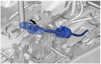
|
(c) Using a screwdriver, pull out the stopper of the transmission control cable assembly. NOTICE: Do not remove the stopper. If it is removed, reinstall it to its original position. |
|
|
(d) Turn the nut of the transmission control cable assembly approximately 180° counterclockwise and, while holding the nut in that position, disconnect the transmission control cable assembly from the transmission floor shift assembly. NOTICE:
|
|
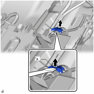
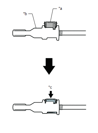
(e) Push the 2 claws together at the top of the lock piece. While holding the 2 claws together, push the 2 lugs on the bottom of the lock piece toward each other and upward to push up the lock piece.
|
*a |
Lock Piece |
*b |
Bottom View |
|
*c |
Push |
*d |
Push up |
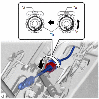
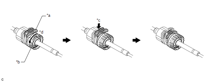
(f) Turn the nut of the transmission control cable assembly approximately 180° counterclockwise. While holding the nut in place, push in the stopper until it clicks twice.
|
*a |
Stopper |
*b |
Nut |
|
*c |
Push in |
*d |
Turn approximately 180° |
HINT:
If the stopper cannot be pushed in, slightly turn the nut clockwise and then push in the stopper again.
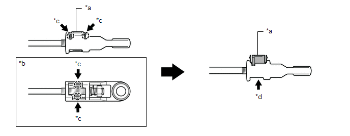
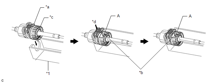
(g) Connect the transmission control cable assembly to the transmission floor shift assembly. Check that the spring is positioned at (A) and push in the stopper.
|
*1 |
Transmission Floor Shift Assembly |
- |
- |
|
*a |
Stopper |
*b |
Spring |
|
*c |
Nut |
*d |
Push in |
NOTICE:
- If the stopper cannot be pushed in, slightly turn the nut clockwise and then push in the stopper again.
- Make sure that the transmission control cable assembly is securely locked.
- Do not forcibly pull the transmission control cable assembly into the cabin.
|
(h) Confirm that the shift lever is in N, and then install the end of the transmission control cable assembly to the transmission floor shift assembly. NOTICE:
|
|
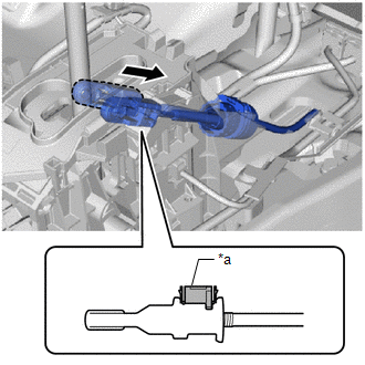
(i) Push the lock piece into the adjuster case.
|
*a |
Lock Piece |
|
*b |
Adjuster Case |
|
*c |
Push in |
NOTICE:
- Check that the park/neutral position switch assembly and shift lever are in N.
- Securely push in the lock piece until the 2 claws are engaged.
- When pushing in the lock piece of the adjuster case to lock it, remove your hand from the lever shaft.
- When pushing in the lock piece of the adjuster case to lock it, do not move
the lever shaft or transmission control cable assembly forward or backward.
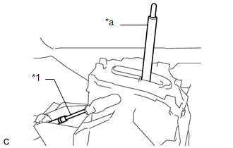
*1
Transmission Control Cable Assembly
*a
Lever Shaft
7. INSTALL NO. 1 CONSOLE BOX DUCT
8. INSTALL NO. 2 CONSOLE BOX DUCT
9. INSTALL NO. 3 CONSOLE BOX DUCT
10. INSTALL CONSOLE BOX ASSEMBLY
Click here
11. INSPECT SHIFT LEVER POSITION
Click here


