Toyota Corolla Cross: Tire Pressure Warning Reset Switch Circuit
DESCRIPTION
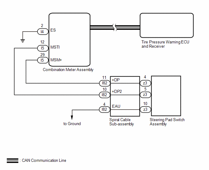
The switch circuit inside the combination meter assembly turns on and off according to the steering pad switch assembly operation.
WIRING DIAGRAM
PROCEDURE
|
1. |
CHECK FOR DTC (CAN COMMUNICATION SYSTEM) |
(a) Check if CAN communication system DTCs are output.
- for Gasoline Model: Click here
.gif)
- for HEV Model: Click here
|
Result |
Proceed to |
|---|---|
|
DTCs are not output. |
A |
|
DTCs are output. |
B |
| B | .gif) |
GO TO CAN COMMUNICATION SYSTEM
|
|
.gif)
|
2. |
INSPECT STEERING PAD SWITCH ASSEMBLY |
Click here
| NG | |
REPLACE STEERING PAD SWITCH ASSEMBLY |
|
|
3. |
INSPECT SPIRAL CABLE SUB-ASSEMBLY |
Click here
| NG | |
REPLACE SPIRAL CABLE SUB-ASSEMBLY |
|
|
4. |
CHECK HARNESS AND CONNECTOR (SPIRAL CABLE SUB-ASSEMBLY - COMBINATION METER ASSEMBLY) |
(a) Disconnect the I82 spiral cable sub-assembly connector.
(b) Disconnect the I4 and I5 combination meter assembly connector.
(c) Measure the resistance according to the value(s) in the table below.
Standard Resistance:
|
Tester Connection |
Condition |
Specified Condition |
|---|---|---|
|
I82-11 (+DP) - I5-29 (MSM+) |
Always |
Below 1 Ω |
|
I82-11 (+DP) or I5-29 (MSM+) - Body ground |
Always |
10 kΩ or higher |
|
I82-10 (+DP2) - I5-12 (MSTI) |
Always |
Below 1 Ω |
|
I82-10 (+DP2) or I5-12 (MSTI) - Body ground |
Always |
10 kΩ or higher |
|
I4-2 (ES) - Body ground |
Always |
Below 1 Ω |
| OK | |
GO TO METER / GAUGE SYSTEM |
| NG | |
REPAIR OR REPLACE HARNESS OR CONNECTOR |


