Toyota Corolla Cross: System Diagram
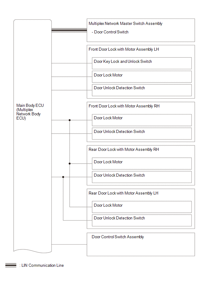
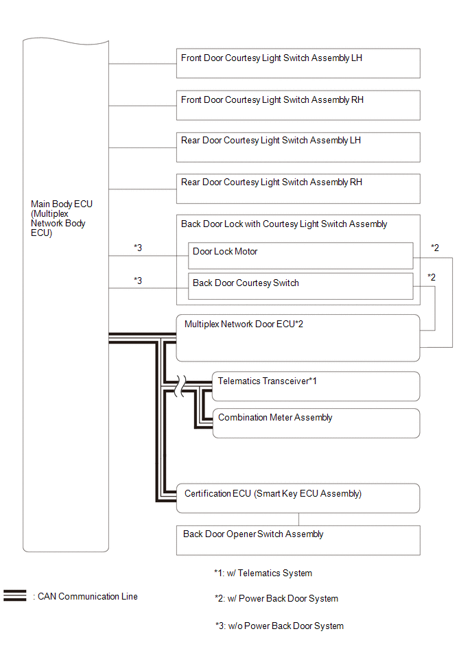
SYSTEM DIAGRAM
READ NEXT:
CAUTION / NOTICE / HINT
HINT:
Use the following procedure to troubleshoot the power door lock control system.
*: Use the GTS.
PROCEDURE
1. VEHICLE BROUGHT TO WORKSHOP
CHECK FOR INTERMITTENT PROBLEMS
NOTICE:
If the vehicle or vehicle controls are operated (for example, during initial inspection when the vehicle is brought in for repair) before vehicle control
OPERATION CHECK CHECK CUSTOMIZE PARAMETERS NOTICE:
The operation check below is based on the non-customized initial condition of the vehicle.
Click here CHECK BASIC FUNCTION
(a) Check that all
SEE MORE:
Removal
REMOVAL
CAUTION / NOTICE / HINT
COMPONENTS (REMOVAL)
Procedure
Part Name Code
1
BACK DOOR OUTSIDE GARNISH SUB-ASSEMBLY
-
-
-
-
2
TELEVIS
DESCRIPTION
These DTCs are stored when a malfunction occurs in the radio
and display receiver assembly.
DTC No.
Detection Item
DTC Detection Condition
Trouble Area
DTC Output from
Priority
B155196
HD-RA
 How To Proceed With Troubleshooting
 Television Camera
