Toyota Corolla Cross: Removal
REMOVAL
CAUTION / NOTICE / HINT
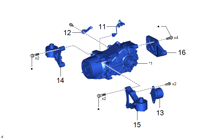
COMPONENTS (REMOVAL)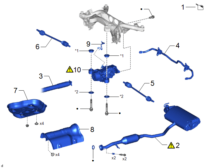
|
Procedure |
Part Name Code |
.png) |
.png) |
.png) |
|
|---|---|---|---|---|---|
|
1 |
DRAIN DIFFERENTIAL OIL |
- |
- |
|
- |
|
2 |
TAIL EXHAUST PIPE ASSEMBLY |
17430 |
|
- |
- |
|
3 |
PROPELLER SHAFT WITH CENTER BEARING ASSEMBLY |
37100 |
- |
- |
- |
|
4 |
REAR STABILIZER BAR |
48812 |
- |
- |
- |
|
5 |
REAR DRIVE SHAFT ASSEMBLY LH |
42340B |
- |
- |
- |
|
6 |
REAR DRIVE SHAFT ASSEMBLY RH |
42330 |
- |
- |
- |
|
7 |
NO. 2 FUEL TANK PROTECTOR |
77642A |
- |
- |
- |
|
8 |
NO. 1 FUEL TANK PROTECTOR |
77641A |
- |
- |
- |
|
9 |
NO. 2 FLOOR WIRE |
82162 |
- |
- |
- |
|
10 |
REAR DIFFERENTIAL CARRIER ASSEMBLY |
- |
|
- |
- |
|
*1 |
REAR UPPER DIFFERENTIAL MOUNT STOPPER |
*2 |
REAR LOWER DIFFERENTIAL MOUNT STOPPER |
|
● |
Non-reusable part |
- |
- |
|
Procedure |
Part Name Code |
|
|
|
|
|---|---|---|---|---|---|
|
11 |
NO. 7 FLOOR WIRE |
8216A |
- |
- |
- |
|
12 |
WIRE HARNESS CLAMP BRACKET |
- |
- |
- |
- |
|
13 |
REAR DIFFERENTIAL DYNAMIC DAMPER |
41196 |
- |
- |
- |
|
14 |
REAR NO. 1 DIFFERENTIAL SUPPORT |
52380 |
- |
- |
- |
|
15 |
REAR NO. 2 DIFFERENTIAL SUPPORT |
52380C |
- |
- |
- |
|
16 |
REAR DIFFERENTIAL SUPPORT |
52391B |
- |
- |
- |
|
*1 |
REAR DIFFERENTIAL CARRIER ASSEMBLY |
- |
- |
|
● |
Non-reusable part |
- |
- |
CAUTION / NOTICE / HINT
The necessary procedures (adjustment, calibration, initialization, or registration) that must be performed after parts are removed and installed, or replaced during the rear differential carrier assembly removal/installation are shown below.
Necessary Procedures After Parts Removed/Installed/Replaced|
Replacement Part or Procedure |
Necessary Procedures |
Effect/Inoperative Function When Necessary Procedures are not Performed |
Link |
|---|---|---|---|
|
Rear wheel alignment adjustment |
|
|
|
|
Reset memory |
Dynamic torque control AWD system |
|
|
|
Suspension, tires, etc. |
Rear television camera assembly optical axis (Back camera position setting) |
Parking assist monitor system |
|
|
Initialize headlight ECU sub-assembly LH |
Automatic headlight beam level control system |
|
CAUTION:
- When the engine is hot, do not touch high-temperature areas such as the
engine or exhaust pipe.
- Touching high-temperature areas such as the engine and exhaust pipe could result in burns.
PROCEDURE
1. DRAIN DIFFERENTIAL OIL
Click here .gif)
2. REMOVE TAIL EXHAUST PIPE ASSEMBLY
|
|
Click here |
3. REMOVE PROPELLER SHAFT WITH CENTER BEARING ASSEMBLY
Click here
4. REMOVE REAR STABILIZER BAR
Click here
5. REMOVE REAR DRIVE SHAFT ASSEMBLY LH
Click here
6. REMOVE REAR DRIVE SHAFT ASSEMBLY RH
Click here
7. REMOVE NO. 2 FUEL TANK PROTECTOR
Click here
8. REMOVE NO. 1 FUEL TANK PROTECTOR
Click here
9. DISCONNECT NO. 2 FLOOR WIRE

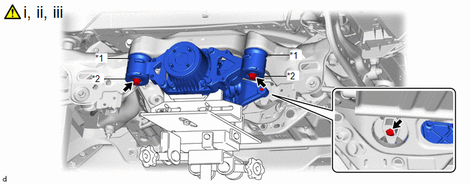
10. REMOVE REAR DIFFERENTIAL CARRIER ASSEMBLY
|
*1 |
Rear Upper Differential Mount Stopper |
*2 |
Rear Lower Differential Mount Stopper |
(1) Support the rear differential carrier assembly with a transmission jack.
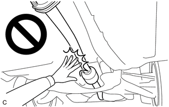
NOTICE:
- The remaining oil may leak out when removing the rear differential carrier assembly.
- Securely support the rear differential carrier assembly while performing this step to avoid excessively tilting or dropping the rear differential carrier assembly.
(2) Remove the 3 bolts and 2 rear lower differential mount stoppers.
(3) Slowly lower the jack and then remove the rear differential carrier assembly and 2 rear upper differential mount stoppers from the rear suspension member sub-assembly.
11. REMOVE NO. 7 FLOOR WIRE

12. REMOVE WIRE HARNESS CLAMP BRACKET

13. REMOVE REAR DIFFERENTIAL DYNAMIC DAMPER

14. REMOVE REAR NO. 1 DIFFERENTIAL SUPPORT

15. REMOVE REAR NO. 2 DIFFERENTIAL SUPPORT

16. REMOVE REAR DIFFERENTIAL SUPPORT