Toyota Corolla Cross: Reassembly
REASSEMBLY
CAUTION / NOTICE / HINT
COMPONENTS (REASSEMBLY)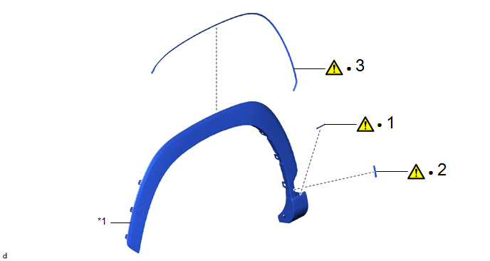
|
Procedure | Part Name Code |
.png) |
.png) |
 |
|---|---|---|---|---|---|
|
1 | NO. 5 FRONT WHEEL OPENING EXTENSION PAD |
53855B |
|
- | - |
|
2 | NO. 3 FRONT WHEEL OPENING EXTENSION PAD |
53853 |
|
- | - |
|
3 | NO. 4 FRONT WHEEL OPENING EXTENSION PAD |
53854 |
|
- | - |
.gif)
|
*1 | FRONT FENDER MOULDING |
- | - |
|
● | Non-reusable part |
- | - |
CAUTION / NOTICE / HINT
HINT:
- Use the same procedure for the RH side and LH side.
- The following procedure is for the LH side.
PROCEDURE
1. INSTALL NO. 5 FRONT WHEEL OPENING EXTENSION PAD
|
|
NOTICE: When installing a new No. 5 front wheel opening extension pad, heat the front fender moulding using a heat light. |
Standard:
|
Item | Temperature |
|---|---|
|
Front Fender Moulding |
20 to 30°C (68 to 86°F) |
CAUTION:
- Do not touch the heat light and heated parts.
- Touching the heat light may result in burns.
- Touching heated parts for a long time may result in burns.
.png)
|
*a | Heated Part |
|
*b | Heat Light |
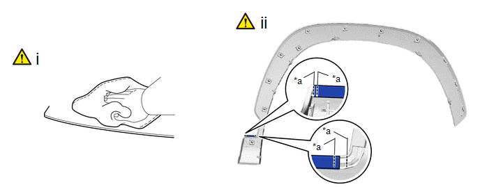
NOTICE:
Do not heat the front fender moulding excessively.
|
*a | Location Line |
- | - |
(1) Clean the front fender moulding.
1. Using a heat light, heat the front fender moulding surface.
2. Remove any remaining double-sided tape from the front fender moulding.
3. Wipe off any tape adhesive residue with cleaner.
NOTICE:
- Installing the No. 5 front wheel opening extension pad with some double-sided tape remaining may cause poor adhesion. Perform this procedure until the tape is sufficiently removed.
- Make sure to use a cloth when removing. Using a screwdriver, etc., may cause damage and poor adhesion.
(2) Install a new No. 5 front wheel opening extension pad.
1. Using a heat light, heat the front fender moulding.
2. Remove the release paper from the No. 5 front wheel opening extension pad.
HINT:
After removing the release paper, keep the exposed adhesive free from foreign matter.
3. Install the No. 5 front wheel opening extension pad as shown in the illustration.
HINT:
- Make sure that the end of the No. 5 front wheel opening extension pad is between the location lines.
- Press the No. 5 front wheel opening extension pad firmly to install it.
2. INSTALL NO. 3 FRONT WHEEL OPENING EXTENSION PAD
|
|
NOTICE: When installing a new No. 3 front wheel opening extension pad, heat the front fender moulding using a heat light. |
Standard:
|
Item | Temperature |
|---|---|
|
Front Fender Moulding |
20 to 30°C (68 to 86°F) |
CAUTION:
- Do not touch the heat light and heated parts.
- Touching the heat light may result in burns.
- Touching heated parts for a long time may result in burns.
|
*a | Heated Part |
|
*b | Heat Light |
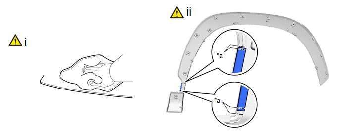
NOTICE:
Do not heat the front fender moulding excessively.
|
*a | Location Line |
- | - |
(1) Clean the front fender moulding.
1. Using a heat light, heat the front fender moulding surface.
2. Remove any remaining double-sided tape from the front fender moulding.
3. Wipe off any tape adhesive residue with cleaner.
NOTICE:
- Installing the No. 3 front wheel opening extension pad with some double-sided tape remaining may cause poor adhesion. Perform this procedure until the tape is sufficiently removed.
- Make sure to use a cloth when removing. Using a screwdriver, etc., may cause damage and poor adhesion.
(2) Install a new No. 3 front wheel opening extension pad.
1. Using a heat light, heat the front fender moulding.
2. Remove the release paper from the No. 3 front wheel opening extension pad.
HINT:
After removing the release paper, keep the exposed adhesive free from foreign matter.
3. Install the No. 3 front wheel opening extension pad as shown in the illustration.
HINT:
- Make sure that the end of the No. 3 front wheel opening extension pad is between the location lines.
- Press the No. 3 front wheel opening extension pad firmly to install it.
3. INSTALL NO. 4 FRONT WHEEL OPENING EXTENSION PAD
|
|
NOTICE: When installing a new No. 4 front wheel opening extension pad, heat the front fender moulding using a heat light. |
Standard:
|
Item | Temperature |
|---|---|
|
Front Fender Moulding |
20 to 30°C (68 to 86°F) |
CAUTION:
- Do not touch the heat light and heated parts.
- Touching the heat light may result in burns.
- Touching heated parts for a long time may result in burns.
|
*a | Heated Part |
|
*b | Heat Light |
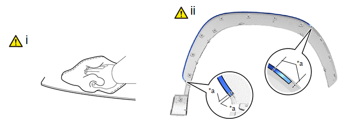
NOTICE:
Do not heat the front fender moulding excessively.
|
*a | Location Line |
- | - |
(1) Clean the front fender moulding.
1. Using a heat light, heat the front fender moulding surface.
2. Remove any remaining double-sided tape from the front fender moulding.
3. Wipe off any tape adhesive residue with cleaner.
NOTICE:
- Installing the No. 4 front wheel opening extension pad with some double-sided tape remaining may cause poor adhesion. Perform this procedure until the tape is sufficiently removed.
- Make sure to use a cloth when removing. Using a screwdriver, etc., may cause damage and poor adhesion.
(2) Install a new No. 4 front wheel opening extension pad.
1. Using a heat light, heat the front fender moulding.
2. Remove the release paper from the No. 4 front wheel opening extension pad.
HINT:
After removing the release paper, keep the exposed adhesive free from foreign matter.
3. Install the No. 4 front wheel opening extension pad as shown in the illustration.
HINT:
- Make sure that the end of the No. 4 front wheel opening extension pad is between the location lines.
- Press the No. 4 front wheel opening extension pad firmly to install it.


